Controlling the Heating of Rooms

a technology for controlling the heating of rooms and rooms, applied in the direction of storage heaters, domestic heating details, space heating and ventilation details, etc., can solve the problems of losing the opportunity to save energy, the actual energy consumption is controlled by the input control,

Inactive Publication Date: 2014-12-11
BMSHOME
View PDF10 Cites 6 Cited by
  • Summary
  • Abstract
  • Description
  • Claims
  • Application Information

AI Technical Summary

Problems solved by technology

However, actual energy consumption is controlled by the input control which in most applications relies upon manual operation.
A problem therefore exists in that, in many applications, opportunities for saving energy are lost due to non-optimised manual operation.

Method used


Image

  • Controlling the Heating of Rooms
  • Controlling the Heating of Rooms
  • Controlling the Heating of Rooms

Examples


Embodiment Construction
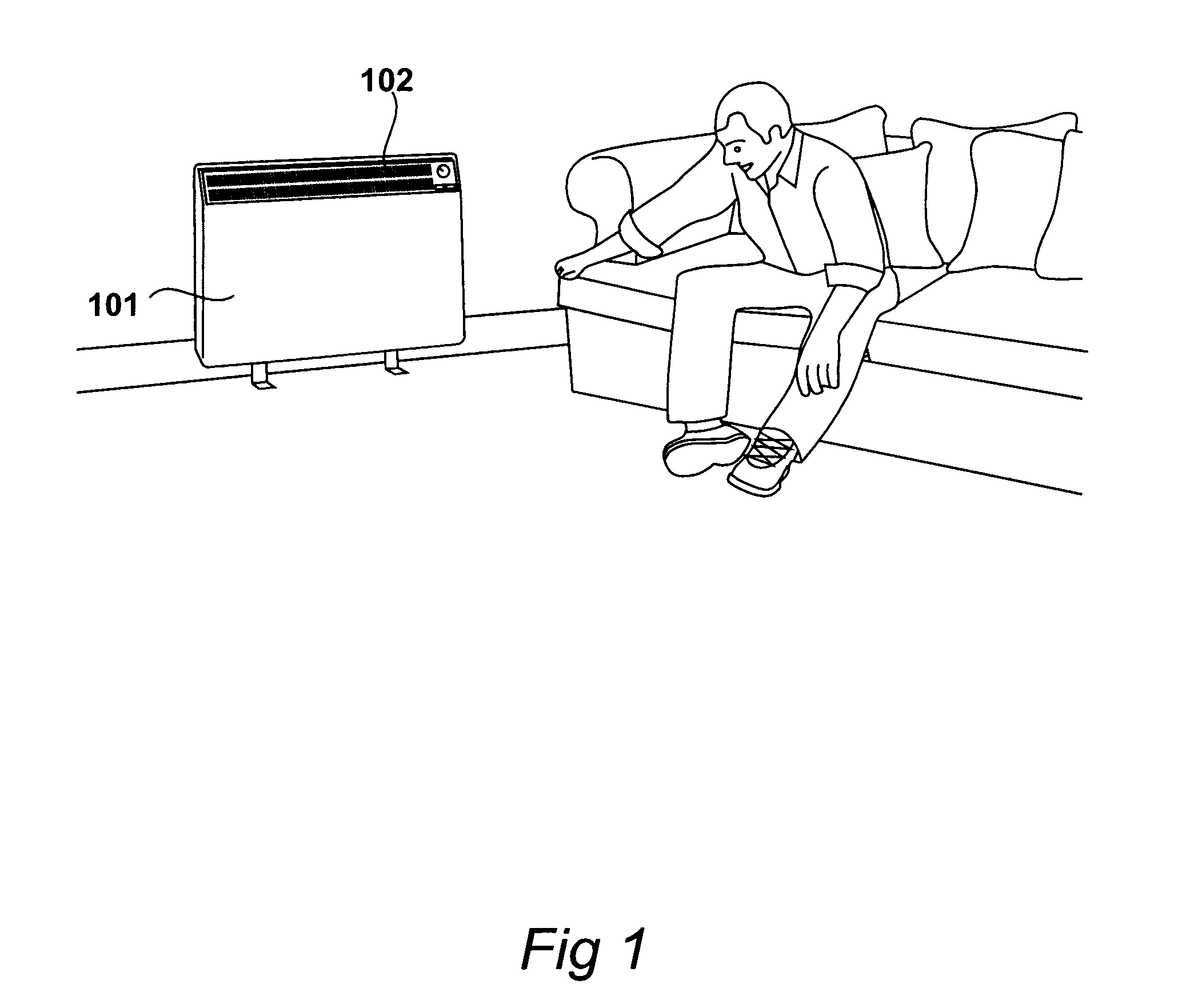
FIG. 1

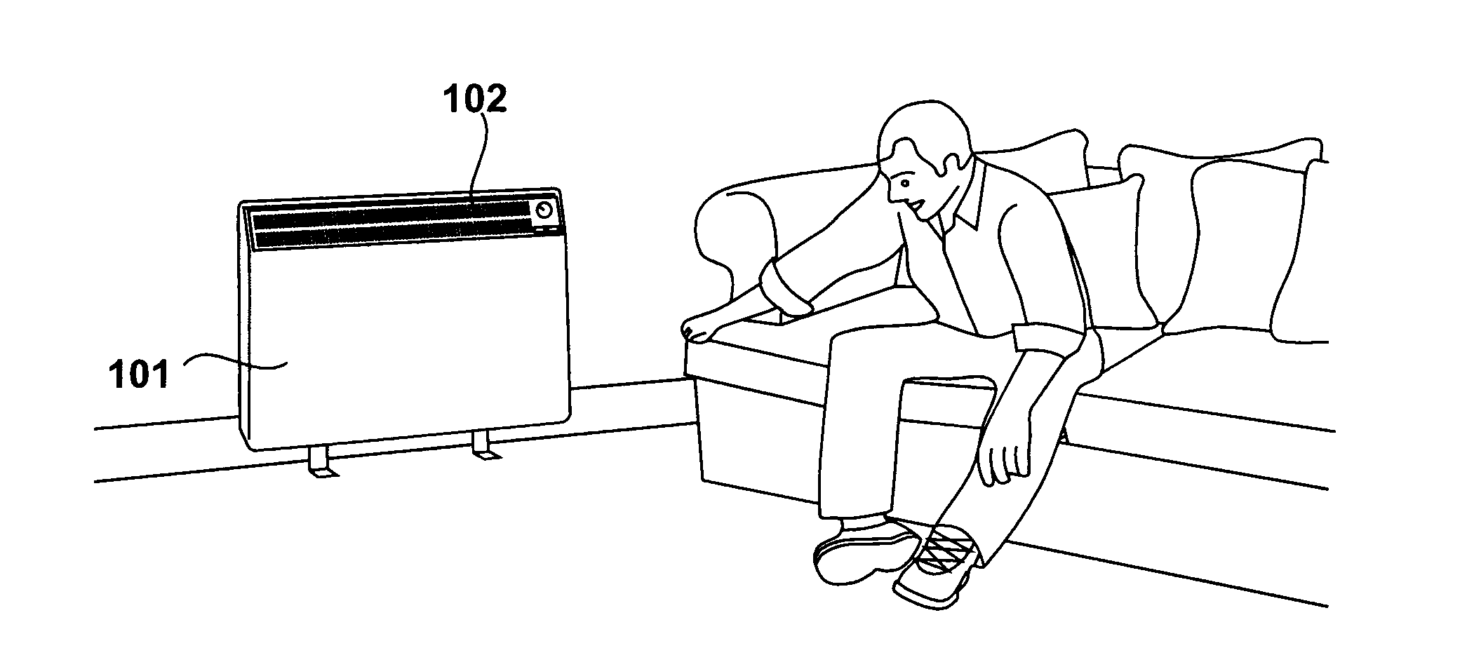
[0021]An electric storage heater 101 is shown in FIG. 1, configured to receive off peak electricity. An electric heater is energised via a local control device in response to a generation schedule. The heater includes an insulated housing for retaining heat storage material and a controllable opening 102 for facilitating heat output. The local control device supplies local data to a building controller. The building controller conveys local data from a plurality of local control devices along with building data to a central control device. The central control device receives regional data and transmits schedules of activation to one or more building control devices. The building control devices relay individual activation schedules to the local control devices.
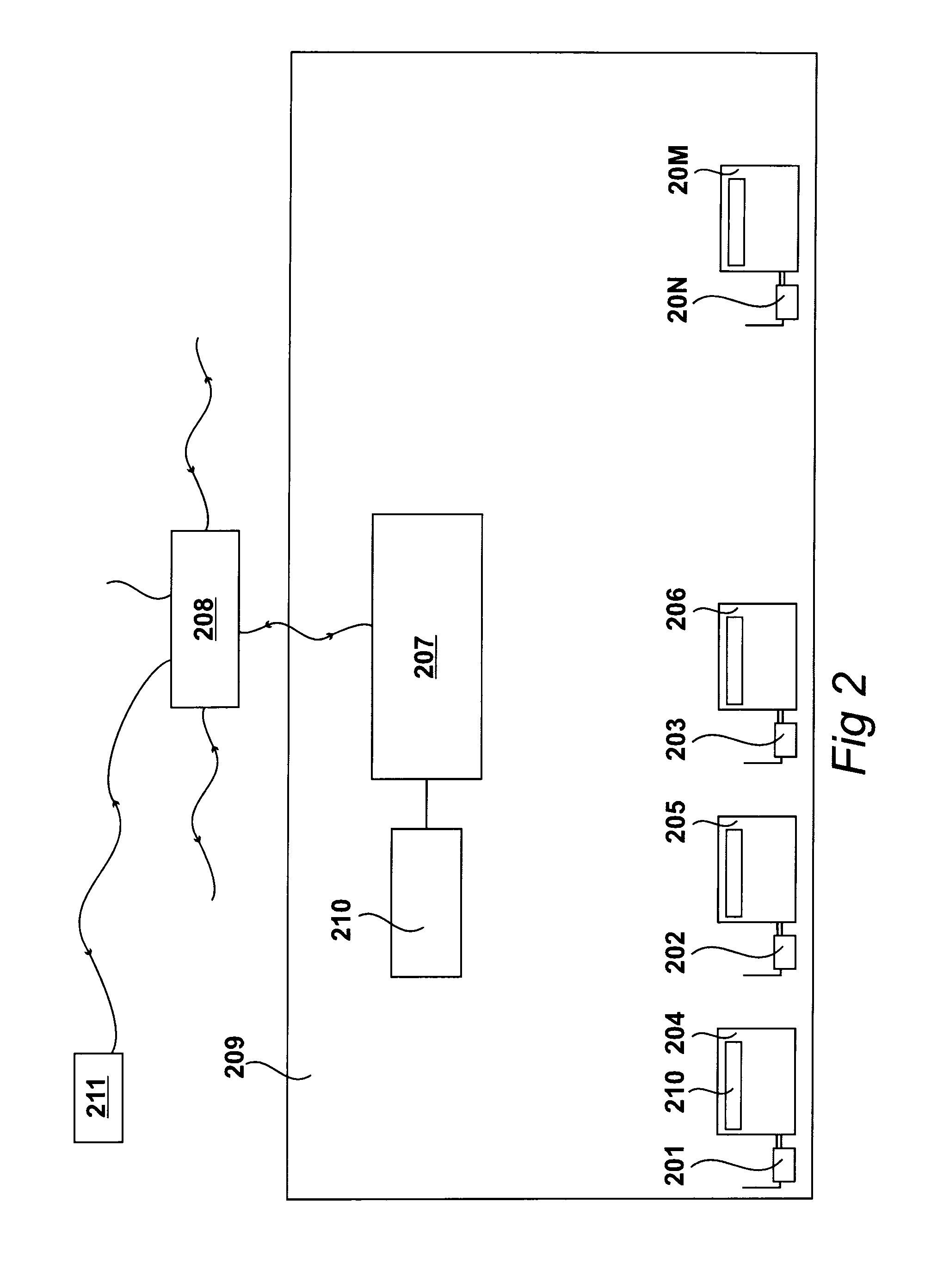
FIG. 2

[0022]Apparatus for heating a plurality of rooms in a plurality of buildings is illustrated in FIG. 2. Local control devices may be included within an electric storage heater, as illustrated in FIG. 1, or the local...


PUM


Abstract

In a building, electric storage heaters (204) receive off peak electricity, generate thermal energy and store this thermal energy for later release. Each storage heater has a local control device (201) for controlling thermal energy generated during the reception of the off peak electricity. Each local control device receives a generation schedule from a building control device (207). Each building control device controls many local control devices and transmits information to a central control device (208). The central control device transmits generation schedules to many building control devices. Each schedule is constructed in response to room related data supplied by the local control devices, building related data supplied by the building control devices and regional data supplied to the central control device.

Description

CROSS REFERENCE TO RELATED APPLICATIONS[0001]This application represents the first application for a patent directed towards the invention and the subject matter.BACKGROUND OF THE INVENTION[0002]1. Field of the Invention[0003]The present invention relates to apparatus for heating a plurality of rooms in a plurality of buildings. The present invention also relates to a method of controlling the amount of electrical energy supplied to electric storage heaters, an electric storage heater and a local control device for an electric storage heater.[0004]2. Description of the Related Art[0005]Storage heaters are known that include electrical heating elements embedded within a heat storage material. They are usually used with a two-tariff electricity meter that records separately the electricity used during peak and off peak periods. Heat generated during off peak periods is then released when required. The extent to which heat is released may be controlled by the opening of louvers and by ...

Claims


Application Information

Patent Timeline
Patent Type & Authority Applications(United States)
IPC IPC(8): G05B15/02
CPCG05B15/02F24H7/002F24H9/2078F24D19/1096G05D23/1923G05B2219/2614G05B2219/2642F24D5/02F24D10/00F24D19/1084G05D23/1934F24H15/172F24H15/20F24H15/443F24H15/37F24H15/486F24H15/254F24H15/262
Inventor HARTLEY, MICHAEL JOHNGAIR, ANTHONY DAVID
Owner BMSHOME
Why Eureka
Try Eureka