Information providing method and information providing apparatus
a technology of information providing apparatus and information providing method, which is applied in the direction of data switching network, instruments, fire alarm radiation actuation, etc., to achieve the effect of improving user-friendliness
- Summary
- Abstract
- Description
- Claims
- Application Information
AI Technical Summary
Benefits of technology
Problems solved by technology
Method used
Image

Examples
embodiment 1
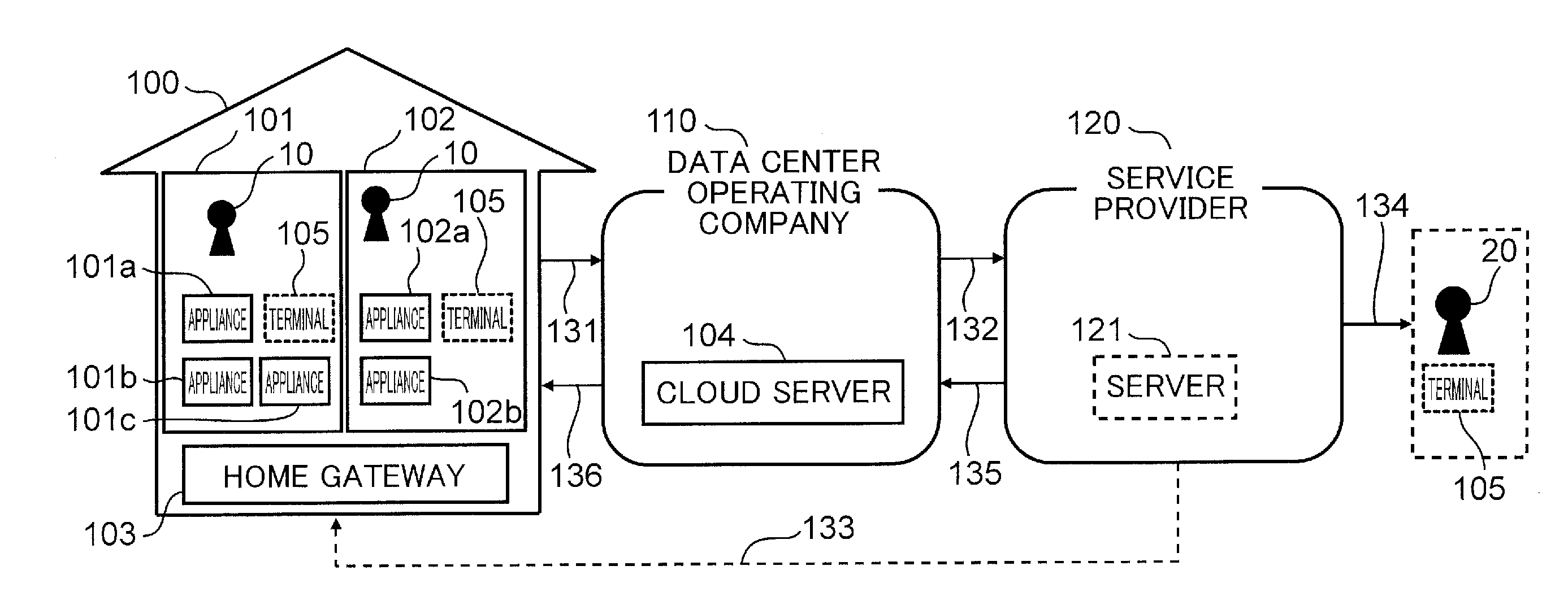
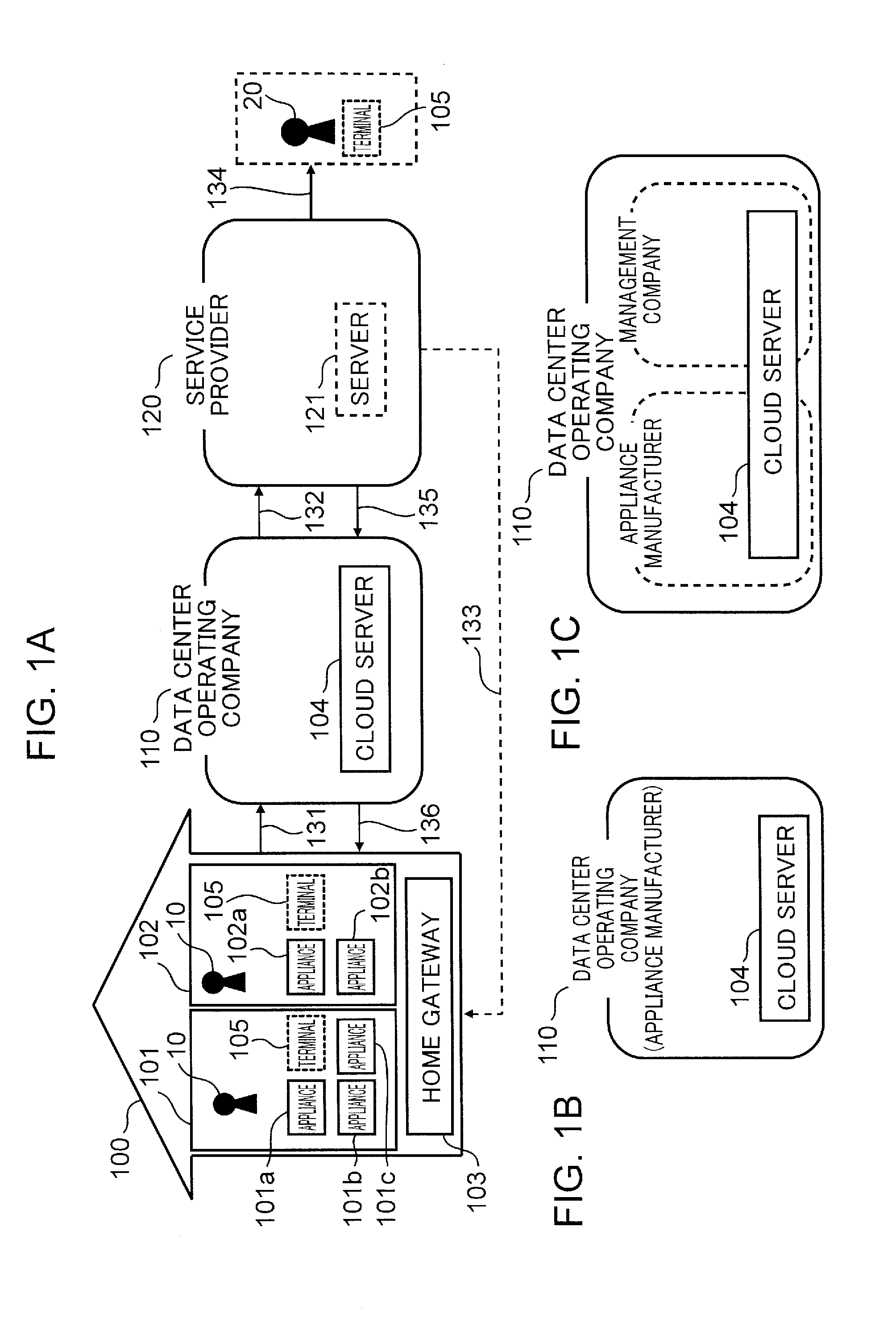
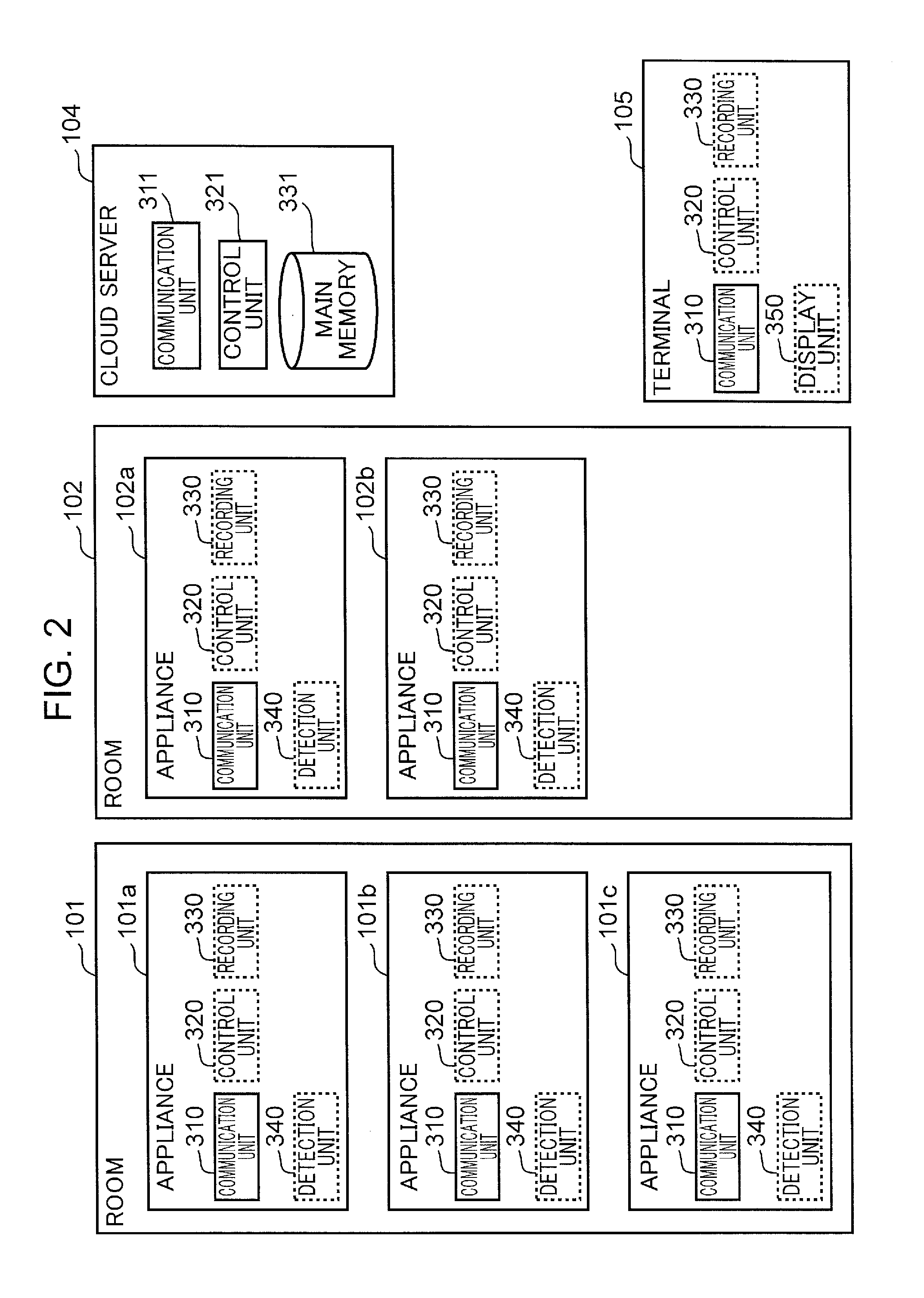
[0112]Embodiment 1 shows an information providing system capable of detecting the location of appliances in a home. FIG. 3 is a diagram showing the overall configuration of the information providing system in embodiment 1. With the information providing system of this embodiment, as shown in FIG. 3, the appliances 101a, 101b, 101c, 102a, 102b are desirably connected to the cloud server 104 via the network 1000. Moreover, desirably, the respective appliances also send, as needed, the operating information of the appliances or the output of the various sensors equipped in the appliances from the communication unit 310 to the cloud server 104 via the network 1000. Note that, while not described in detail in this embodiment, the terminal 105 also comprises, as with the appliances, the communication unit 310 for communicating with the cloud server 104 via the network 1000.
[0113](Configuration of Information Providing System)
[0114]FIG. 4 is a diagram showing the detailed configuration of ...
embodiment 2
[0350]In embodiment 2, explained are examples of the services provided to the user using the respective appliances by using the information that has been detected in the information providing system described in embodiment 1. Note that embodiment 2 is merely an example, and does not in any way limit the services that can be provided by the information providing system described in embodiment 1.
[0351]Based on the appliance identification unit 2001, the room position detection unit 2002, the appliance position detection unit 2003 and the user position detection unit 2004 described in embodiment 1, obtained are (1) same-room appliance list information (first information), (2) positional relationship information of rooms (second information), (3) appliance position information in rooms (third information) and (4) user's position information (fourth information). Moreover, based on the appliance position information and the user's position information, (5) user information of each applia...
embodiment 3
[0463]Embodiment 3 explains examples of the services that are provided to the user to use respective appliances by using the information that has been detected in the information providing system described in embodiment 1. Note that embodiment 3 is merely an example, and does not limit the services that can be provided by the information providing system described in embodiment 1.
[0464]Appliance user information (fifth information) relating to the user of the respective appliances is obtained by the appliance position detection unit 2003 and the user position detection unit 2004 described in embodiment 1.
[0465]FIG. 41 is a diagram showing the service mode in which the service provider receives image information from the imaging device, and receives appliance operating information and intermittent pattern information from the respective appliances installed in the same room. As shown in FIG. 41, the first service provider 120 receives image information from the imaging device 1701, a...
PUM
 Abstract
Description
Claims
Application Information