Die cushion force setting apparatus

a technology of force setting apparatus and die cushion, which is applied in the direction of press ram, manufacturing tools, forging presses, etc., can solve the problems of troublesome operation of setting the force of die cushion on each driving shaft individually, and it is difficult to provide a precise distribution of die cushion forces in the plane of the cushion pad, so as to facilitate the entry of die cushion forces

Active Publication Date: 2014-12-18
AIDA ENG LTD
View PDF3 Cites 11 Cited by
  • Summary
  • Abstract
  • Description
  • Claims
  • Application Information

AI Technical Summary

Benefits of technology

[0021]According to still another aspect of the present invention, the die cushion force setting apparatus further comprises a die cushion position selector used to select one of a plurality of die cushion positions, wherein the die cushion force setting method selector allows one die cushion force setting method to be selected for each die cushion position selected by the die cushion position selector. This makes it possible to select a die cushion force setting method suitable for a die cushion position.
[0022]According to the present invention, in individually setting die cushion forces (component forces) acting on plural driving shafts, since one or more of the plural die cushion forces are numerically computed based on input of one die cushion force and additional information, it is easier to enter die cushion forces than when all the plural die cushion forces are entered manually. Also, since the plural die cushion forces can be associated with one another based on the additional information, it is easy to apply strong or weak die cushion forces to a complex-shaped drawn part in the plane of the cushion pad, making it possible to provide a smooth die cushion force distribution.

Problems solved by technology

In that case, however, when there are a large number of driving shafts to be configured, there is a problem in that the operation of setting the die cushion force individually on each driving shaft becomes troublesome.
Also, there is a problem in that it is difficult to provide a precise distribution of die cushion forces in a plane of the cushion pad for a complex-shaped drawn part because it is difficult to apply a strong or weak die cushion force to a specifically shaped region of the complex-shaped drawn part and also because a total die cushion force acts discontinuously in the cushion pad due to inaccuracy of human sense.

Method used


Image

  • Die cushion force setting apparatus
  • Die cushion force setting apparatus
  • Die cushion force setting apparatus

Examples


Embodiment Construction

[0031]A preferred embodiment of a die cushion force setting apparatus according to the present invention will be described in detail below with reference to the accompanying drawings.

[0032]First, a die cushion apparatus of a press machine resulting from application of a die cushion force setting apparatus according to the present invention will be described.

[0033]

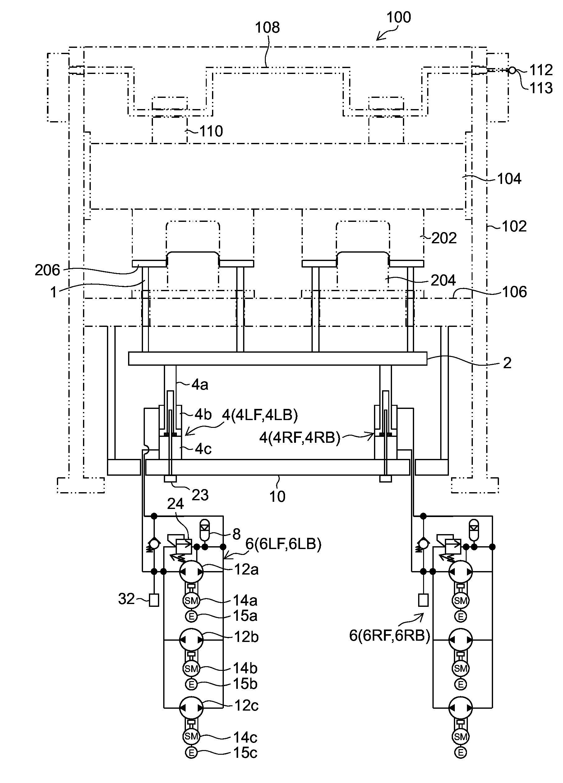
[0034]FIG. 1 is a configuration diagram showing an embodiment of a die cushion apparatus of a press machine. Main components of the press machine are indicated by chain lines.

[0035]The press machine 100 shown in FIG. 1 includes a column (frame) 102, a slide 104, a bed 106, a crankshaft 108, and a connecting rod 110, and slide 104 is movably guided in a vertical direction by a guide unit installed on the column 102. Also, the crankshaft 108 is coupled to the slide 104 via the connecting rod 110. A rotational driving force is designed to be transmitted to the crankshaft 108 via a servomotor and reduction gear mechanism (neith...


PUM

PropertyMeasurementUnit
cushion forcesaaaaaaaaaa
forceaaaaaaaaaa
cushion forceaaaaaaaaaa

Abstract

The die cushion force setting apparatus according to an aspect of the present invention allows die cushion forces (component forces) acting on plural driving shafts to be set easily, makes it easy to apply strong or weak die cushion forces to a complex-shaped drawn part in a plane of a cushion pad, and provides a smooth die cushion force distribution. An operator manually enters a total die cushion force, axial component force of a left front hydraulic cylinder, and center-of-force position by operating an input device. Based on the information entered via the input device, the numerical computing device B1 calculates axial component forces of three hydraulic cylinders through numerical computations. The one axial component force thus entered and three axial component forces thus computed numerically are set as the axial component forces of four hydraulic cylinders.

Description

BACKGROUND OF THE INVENTION[0001]1. Field of the Invention[0002]The present invention relates to a die cushion force setting apparatus, and more particularly, to a die cushion force setting apparatus adapted to individually set die cushion forces (component forces) acting on plural driving shafts which support a cushion pad of a die cushion apparatus.[0003]2. Description of the Related Art[0004]Conventionally, a die cushion pin pressure control apparatus has been proposed for a die cushion apparatus which supports a cushion pad using plural hydraulic cylinders, wherein the hydraulic cylinders are divided into plural groups, a hydraulic supply line is installed for each group to supply hydraulic pressure to the group from a hydraulic pressure feeder, hydraulic-pressure adjustment mechanism (pressure control valve) is disposed in each hydraulic supply line, and die cushion pressure is controlled independently for each hydraulic cylinder (Japanese Utility Model Application Laid-Open No...

Claims


Application Information

Patent Timeline
Patent Type & Authority Applications(United States)
IPC IPC(8): B21D24/02G05B19/46
CPCG05B19/46B21D24/02B21D24/10B30B1/26B30B15/061B30B15/14
Inventor KOHNO, YASUYUKITSUCHIDA, KAZUFUMIMAKABE, JUNJI
Owner AIDA ENG LTD
Why Eureka
Try Eureka