Electric Mitre Saw

a technology of electric mitre saw and sliding shaft, which is applied in the direction of metal sawing device, manufacturing tools, portability drilling machines, etc., can solve the problems of large packing dimension, high delivery cost, and large working space of sliding type miter saw, so as to facilitate operation and reduce fabrication difficulty level, the effect of greatly reducing the guide rod length

Active Publication Date: 2014-12-18
SUMEC HARDWARE & TOOLS
View PDF25 Cites 5 Cited by
  • Summary
  • Abstract
  • Description
  • Claims
  • Application Information

AI Technical Summary

Benefits of technology

[0037]1. The electric mitre saw of the present invention has multiple layers of guide rods arranged between the saw unit and the worktable, and thus the length of the guide rods can be greatly shortened to achieve the same cutting stroke when compared with the prior art designs, and thus the fabrication difficulty level can be relatively lowered.
[0038]2. The multiple layers of guide rods can be respectively locked in different positions so that the user can set the sliding stroke subject to the workpiece cutting width, facilitating operation and enhancing the working efficiency.
[0039]3. When the saw unit is moved back to the swinging arm, the guide rods will not extend out of the rear side of the swinging arm, or the extended distance of the guide rods out of the rear side of the swinging arm is limited, at this time, the working space of the electric mitre saw is greatly reduced, reducing the packing dimension of the electric mitre saw and its transportation cost.
[0040]4. If two layers of guide rods are respectively arranged at two opposite lateral sides relative to the saw blade, the guide rods do not interfere with the cutting operation of the saw blade; a connection member is connected between the two guide rods of each layer to limit the sliding of the sliding block and to increase the parallelity of the guide rods, and thus, the guide rods can be made relatively longer to provide a relatively larger cutting stroke.
[0041]5. If two layers of guide rods are respectively arranged at two opposite lateral sides relative to the saw blade, the planes on the two layers of guide rods define therebetween a V-shaped open space that has a relatively larger top side facing toward the saw unit for the passing of the motor mount and the saw blade and a relatively smaller bottom side facing toward the worktable for the passing of the saw blade, and thus, a wide viewing angle is provided, facilitating viewing the cutting operation.

Problems solved by technology

During operation of a sliding type miter saw of this design, the at least one sliding rail will extend backward, and therefore the sliding type miter saw requires a large working space.
Further, a sliding type miter saw of this design has the drawbacks of large packing dimension and high delivery cost.
However, due to a single layer sliding rail arrangement, the sliding stroke is limited.
However, this design of sliding type miter saw still requires a large working space and has a large packing dimension.
This design fully utilizes the space above the base, however, the sliding rail will extend out of the base to a long distance during the operation.

Method used


Image

  • Electric Mitre Saw
  • Electric Mitre Saw
  • Electric Mitre Saw

Examples


Embodiment Construction

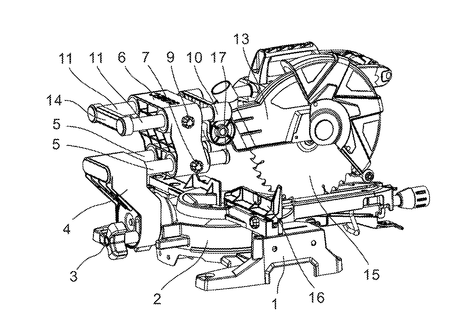
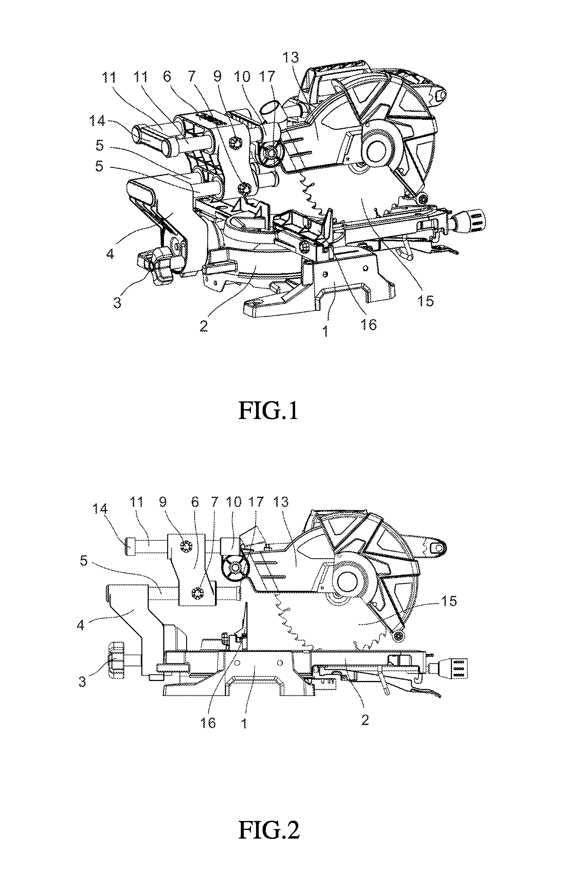
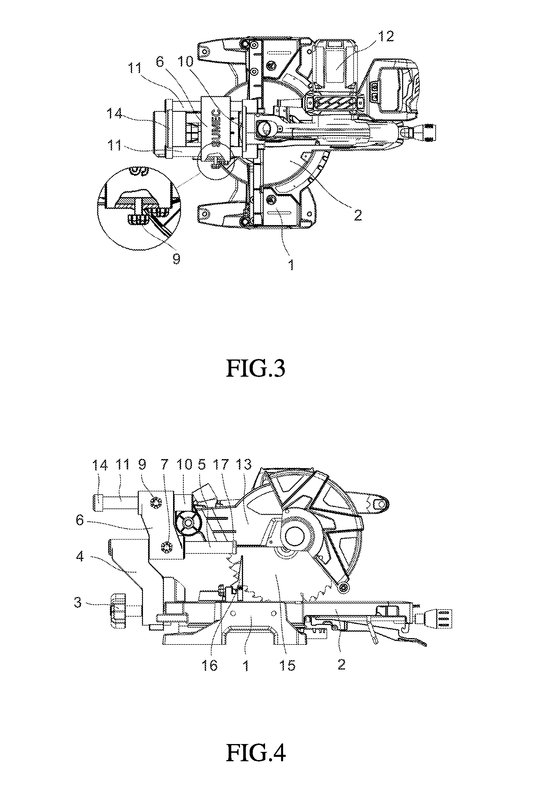
[0053]Referring to FIGS. 1, 2 and 3, a electric mitre saw in accordance with a first embodiment of the present invention is shown. According to this first embodiment, the electric mitre saw comprises a base 1, a fence 16 mounted at the base 1 for supporting the workpiece to be cut, a worktable 2 rotatably coupled to the base 1, a swinging arm 4 pivotally mounted at a rear side of the worktable 2, an arm locking knob 3 located at a rear side of the swinging arm 4 and adapted for locking the swinging arm 4 to the worktable 2 at a selected angle, at least one, for example, two first-layer guide rods 5 mounted in and horizontally extended out of the swinging arm 4, a sliding block 6 mounted on and movable along the first-layer guide rods 5, at least one, for example, two second-layer guide rods 11 slidably mounted in the sliding block 6 in parallel to the first-layer guide rods 5, a rotating shaft 10 fixedly mounted at one end of the second-layer guide rods 11, and a saw unit pivotally ...


PUM

PropertyMeasurementUnit
electricaaaaaaaaaa
angleaaaaaaaaaa
lengthaaaaaaaaaa

Abstract

Disclosed is an electric mitre saw, comprising a base (1), a work bench (2), a saw mechanism, and a swing arm (4), wherein a plurality of layers of slide rails (5, 11) extending in a horizontal direction are provided on the swing arm (4), with the plurality of layers of slide rails (5, 11) being able to slide horizontally relative to each other by means of a slide block (6), a rotary shaft (10) is provided on one layer of the slide rails (11) farthest away from the swing arm (4), and the saw mechanism is rotatably connected to the rotary shaft (10). By means of the arrangement of the plurality of layers of slide rails (5, 11), the length of each layer of slide rails is relatively short, the manufacturing difficulty is reduced, there is a saving in the working space of the miter saw, and the packaging volume is reduced. When one layer of slide rails (5, 11) is respectively arranged at both sides of a saw blade (15), the end parts of two slide rails of each layer of slide rails (5, 11) are able to be connected by a connecting seat (8, 14), thus facilitating the improvement of parallelism of the two slide rails (5, 11), and providing a greater cutting travel. A gripping space is also formed between the two layers of slide rails (5, 11), such that observation during cutting is convenient.

Description

BACKGROUND OF THE INVENTION[0001]1. Field of the Invention[0002]The present invention relates to miter saw technology, and more particularly to a sliding type electric mitre saw.[0003]2. Description of the Related Art[0004]For the advantage of being capable of making a quick, accurate, wide crosscut in a workpiece at a selected angle, sliding type miter saws have been widely used in various fields. In the prior art, most sliding type miter saws have a swinging arm mounted at a rear side of the worktable, at least one sliding rail slidably mounted at the swinging arm, and a sawing mechanism fixedly mounted at one end of the sliding rail, thereby providing a sliding cutting function. During operation of a sliding type miter saw of this design, the at least one sliding rail will extend backward, and therefore the sliding type miter saw requires a large working space. Further, a sliding type miter saw of this design has the drawbacks of large packing dimension and high delivery cost. U....

Claims


Application Information

Patent Timeline
Patent Type & Authority Applications(United States)
IPC IPC(8): B23D47/02B27B5/20B23D45/14
CPCB23D47/02B27B5/208B23D45/14B23D45/048Y10T83/7697B23B45/048
Inventor LIN, YOUYU
Owner SUMEC HARDWARE & TOOLS
Why Eureka
Try Eureka