Fuel Apportionment for Multi Fuel Engine System

a fuel apportionment and engine technology, applied in the direction of engine controllers, machines/engines, fuel injection control, etc., can solve the problems of limiting the available fuel supply, requiring multiple pi controllers, and requiring significant design time and effor

Inactive Publication Date: 2014-12-18
CATERPILLAR MOTOREN
View PDF14 Cites 24 Cited by
  • Summary
  • Abstract
  • Description
  • Claims
  • Application Information

AI Technical Summary

Benefits of technology

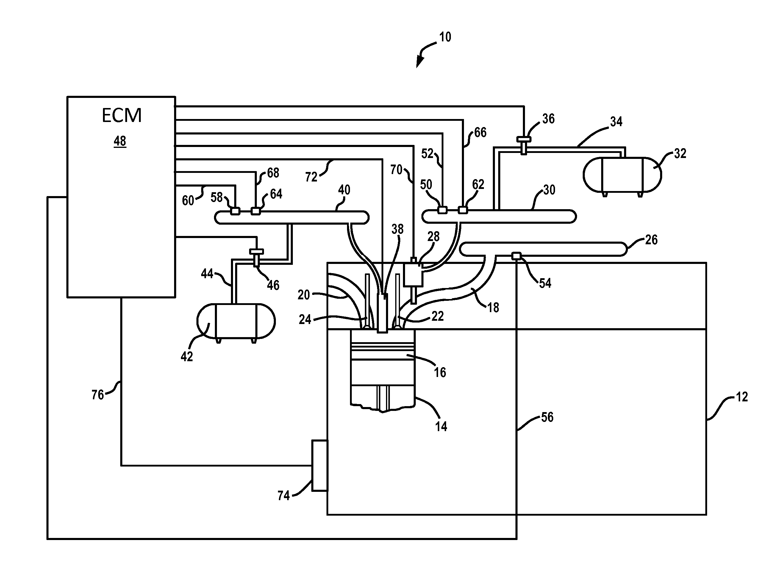
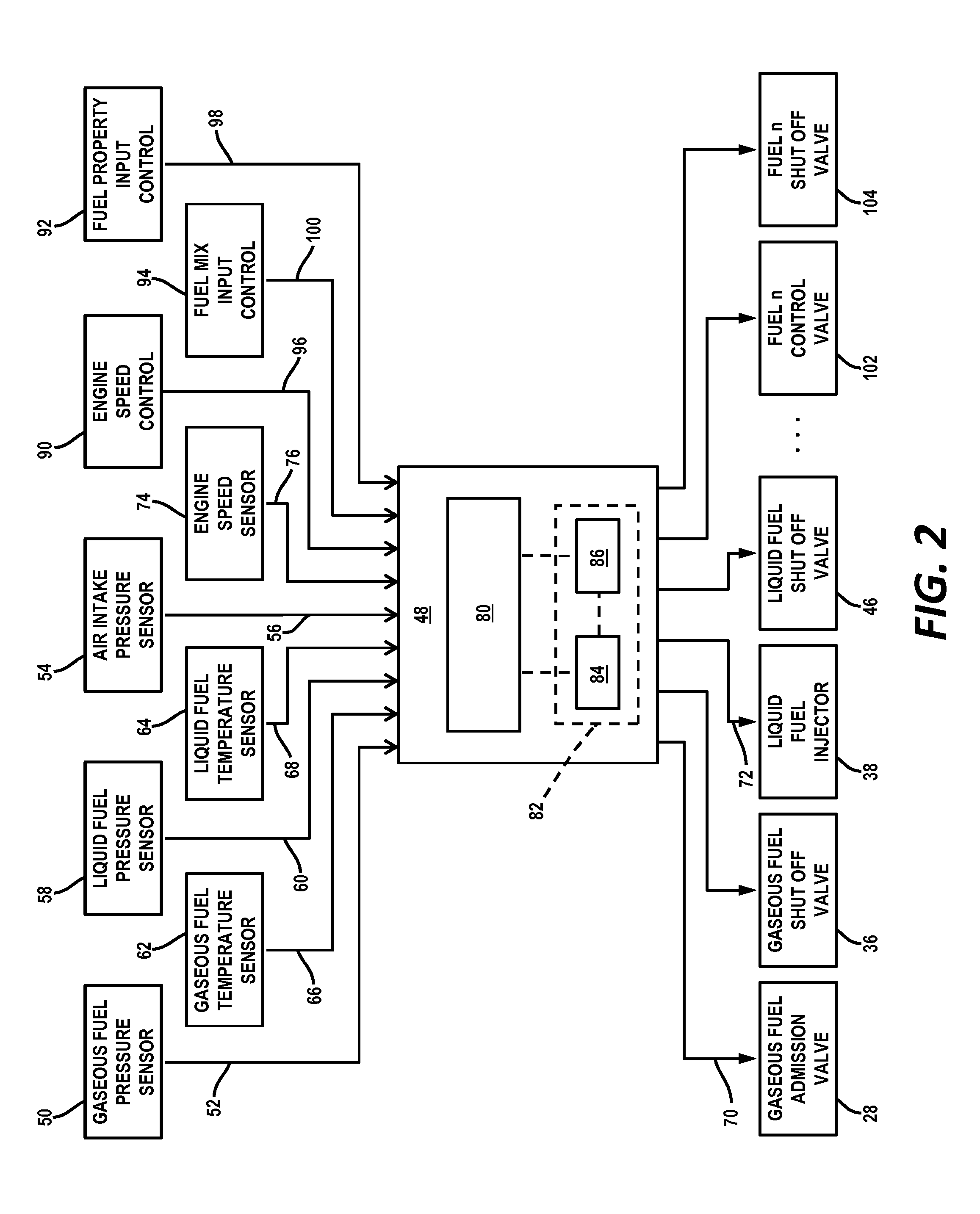
[0007]In one aspect of the present disclosure, a method for controlling fuel flow in a multi fuel engine is disclosed. The method may include determining an input power for operating the multi fuel engine at a desired engine speed, determining a fuel flow rate for each of a plurality of fuels available for providing power to the multi fuel engine based on the input power and a specifi

Problems solved by technology

In combat settings, for example, enemy action or unit isolation may limit the available fuel supply and personnel may need to resort the type of fuel available for usage from enemy and civilian sources.
However, typical speed controllers (usually proportional-integral controllers, commonly called PI controllers) can only set a fuel rate for a single fuel.
The disadvantages of this type of control structure include the significant amount of design time and effort required for multiple PI controllers and the complexity of the switching strategy to ensure that the overall design is robust and responsive to changes in the

Method used


Image

  • Fuel Apportionment for Multi Fuel Engine System
  • Fuel Apportionment for Multi Fuel Engine System
  • Fuel Apportionment for Multi Fuel Engine System

Examples


Embodiment Construction

[0016]Although the following text sets forth a detailed description of numerous different embodiments of the present disclosure, it should be understood that the legal scope of protection is defined by the words of the claims set forth at the end of this patent. The detailed description is to be construed as exemplary only and does not describe every possible embodiment since describing every possible embodiment would be impractical, if not impossible. Numerous alternative embodiments could be implemented, using either current technology or technology developed after the filing date of this patent, which would still fall within the scope of the claims defining the scope of protection.

[0017]It should also be understood that, unless a term is expressly defined in this patent using the sentence “As used herein, the term ‘______’ is hereby defined to mean . . . ” or a similar sentence, there is no intent to limit the meaning of that term, either expressly or by implication, beyond its p...


PUM


Abstract

A method for controlling fuel flow to apportion a plurality of available fuels in a multi fuel engine is disclosed. An input power for operating the multi fuel engine at a desired engine speed is determined at a PI controller, and a fuel flow rate for each of a plurality of available fuels is determined at a fuel apportionment module based on the required input power and a specified fuel substitution ratio for apportioning the plurality of fuels to the multi fuel engine. Fuel flow commands for each of the plurality of fuels are output to corresponding actuators of fluid flow control devices for the fuels to cause the cause the fluid flow control devices to provide the corresponding fuels to the multi fuel engine at the corresponding fuel flow rate.

Description

TECHNICAL FIELD[0001]The present disclosure relates generally to multi fuel engines capable of operating with liquid fuel, with gaseous fuel and with a mixture of liquid and gaseous fuels, and more particularly, to methods and systems for controlling the apportionment of the multiple fuels to the multi fuel engine to meet the input power demand with a desired mixture of the multiple fuels.BACKGROUND[0002]A multi fuel engine refers generically to any type of engine, boiler, heater or other fuel-burning device which is designed to burn multiple types of fuels in its operation. Multi fuel engines have application in diverse areas to meet particular operational needs in the operating environment. For example, a common use of multi fuel engines is in military vehicles so that vehicles in various deployment locations may run a wide range of alternative fuels such as gasoline, diesel or aviation fuel. In combat settings, for example, enemy action or unit isolation may limit the available f...

Claims


Application Information

Patent Timeline
IPC IPC(8): F02D41/00
CPCF02D41/0025F02D19/061F02D19/0628F02D19/0647F02D19/081F02D19/105F02D31/007F02D41/0027F02D2200/0602F02D2200/0606F02D2200/101Y02T10/30
Inventor SIVASUBRAMANIAN, ARVINDGALLMEYER, CHRISTOPHER F.
Owner CATERPILLAR MOTOREN
Why Eureka
Try Eureka