Multifuel gas turbine combustor

a gas turbine and combustor technology, applied in the direction of turbine/propulsion fuel valves, machines/engines, lighting and heating apparatus, etc., can solve problems such as heat loss and/or impairment, and achieve the effect of low nox and low emission performan

Active Publication Date: 2015-12-17
KAWASAKI HEAVY IND LTD
View PDF6 Cites 12 Cited by
  • Summary
  • Abstract
  • Description
  • Claims
  • Application Information

AI Technical Summary

Benefits of technology

[0009]In view of the foregoing, the present invention has for its primary object to provide a multifuel gas turbine combustor, that is, a gas turbine combustor capable of operating with mult

Problems solved by technology

Accordingly, if a substantial amount of the hydrogen gas is mixed in the fuel for the dry low emission combustor, there is a possibility that the back fir

Method used


Image

  • Multifuel gas turbine combustor
  • Multifuel gas turbine combustor
  • Multifuel gas turbine combustor

Examples


third embodiment

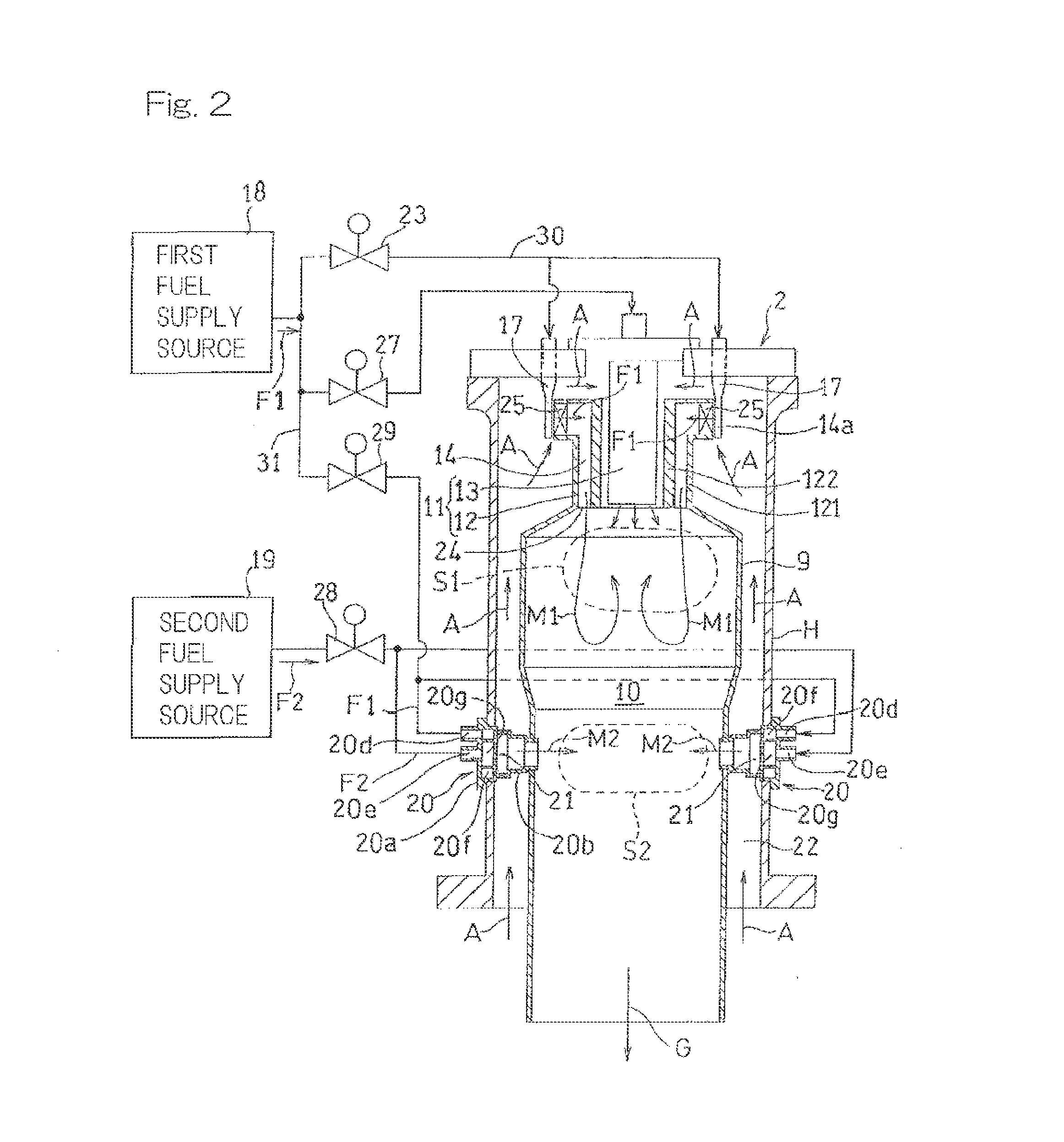
[0049]Since the gas turbine combustor 2B according to this third embodiment is such that the first reheating fuel supply passage 31 is fluid connected with the main fuel supply passage 30 at a location upstream of the first fuel control valve 23, it is possible to stably supply at all times a predetermined amount of the first fuel F1 to the supplemental burner 20B, regardless of pressure fluctuation within the main fuel supply passage 30 accompanied by an adjustment of the first fuel control valve 23.

[0050]A fourth preferred embodiment of the present invention is shown in FIG. 7. It is to be noted that in FIG. 7, components similar to those shown in FIG. 2 and described in connection with the previously described embodiment are designated by similar or identical reference numerals that are employed in FIG. 2 and, therefore, the details thereof are not reiterated for the sake of brevity. The gas turbine combustor 2C, employed in the practice of this fourth embodiment, includes a plur...

fourth embodiment

[0051]In the gas turbine combustor 2C according to this fourth embodiment, besides the supply of the first fuel F1 through the second fuel control valve 27 and the check valve 38, the second fuel F2 containing the hydrogen gas is supplied to the pilot burner 13A through the sixth fuel control valve 39. Therefore, combustion occurring in the pilot burner 13A is stabilized by the hydrogen gas having a high combustion temperature.

[0052]Although the present invention has been fully described in connection with the preferred embodiments thereof with reference to the accompanying drawings which are used only for the purpose of illustration, those skilled in the art will readily conceive numerous changes and modifications within the framework of obviousness upon the reading of the specification herein presented of the present invention. Accordingly, such changes and modifications are, unless they depart from the scope of the present invention as delivered from the claims annexed hereto, to...


PUM


Abstract

To provide a multifuel gas turbine combustor capable of combusting gases containing hydrogen in a high concentration with a low NOx while maintaining a low emission performance brought about by the pre-mixture combustion in the main burner, the gas turbine combustor includes a main burner (12) for supplying to and combusting a premixed gas (M), containing a first fuel (F1), within a first combustion region (S1) of a combustion chamber (10), and a supplemental burner (20) for supplying to and combusting a second fuel (F2) of a composition different from that of the first fuel (F1) within a second combustion region (S2) defined downstream of the first combustion region (S1) within the combustion chamber (10). The first fuel (F1) is of a hydrocarbon system and the second fuel (F2) is a gas containing hydrogen in a concentration exceeding the stable combustion limiting concentration of the hydrogen.

Description

CROSS-REFERENCE TO RELATED APPLICATIONS [0001]This is a continuation of U.S. patent application Ser. No. 14 / 421,065, filed Feb. 11, 2015, which is a 371 National Stage entry of PCT / JP2014 / 065657, filed Jun. 12, 2014. The entire disclosure of the prior application is considered part of the disclosure of the accompanying divisional application, and is hereby incorporated by reference.BACKGROUND OF THE INVENTION [0002]1. Field of the Invention[0003]The present invention relates to a multifuel gas turbine combustor operable with the efficient utilization of hydrogen containing fuel while securing a low emission performance.[0004]2. Description of Related Art[0005]In the field of combustors in gas turbine engines, a technology for securing a low emission performance including a low NOx emission has hitherto been known, which includes, besides a wet type combustor, in which water or steam is injected into the combustor, a dry low emission (DLE) combustor in which a pre-mixture formed by m...

Claims


Application Information

Patent Timeline
IPC IPC(8): F23R3/36F23R3/28F23R3/34F02C3/22
CPCF23R3/36F23R3/343F23R3/286F02C3/22F23R3/346F23R3/46F23R2900/00002F02C7/222F02C7/232F02C9/40F23C2900/9901F23D2900/00015F23R3/34
Inventor OGATA, MASAHIROODA, TAKEOKINOSHITA, YASUHIRO
Owner KAWASAKI HEAVY IND LTD
Why Eureka
Try Eureka