Joint Including Two Sections Of A Power Cable And A Method For Joining Two Sections Of A Power Cable

a technology of power cables and connectors, which is applied in the manufacture of power cables, electrically conductive connections, cable/conductor manufacturing, etc., can solve the problems of loss of natural torsional rigidity of cables, heavy weight of double armouring wires, and functional impairment of armouring wires

Active Publication Date: 2014-12-18
NKT HV CABLES AB
View PDF5 Cites 6 Cited by
  • Summary
  • Abstract
  • Description
  • Claims
  • Application Information

AI Technical Summary

Benefits of technology

[0010]An object of the present invention is to alleviate the above mentioned problems with jointed sin

Problems solved by technology

Since a double armouring wire is heavy and expensive to produce, it is only used in a few applications that require extra strengthening of the cable.
A problem with mounting a stiff three part joint between the cable sections of a single armoured cable is that the natural torsional rigidity of the c

Method used


Image

  • Joint Including Two Sections Of A Power Cable And A Method For Joining Two Sections Of A Power Cable
  • Joint Including Two Sections Of A Power Cable And A Method For Joining Two Sections Of A Power Cable
  • Joint Including Two Sections Of A Power Cable And A Method For Joining Two Sections Of A Power Cable

Examples


Embodiment Construction

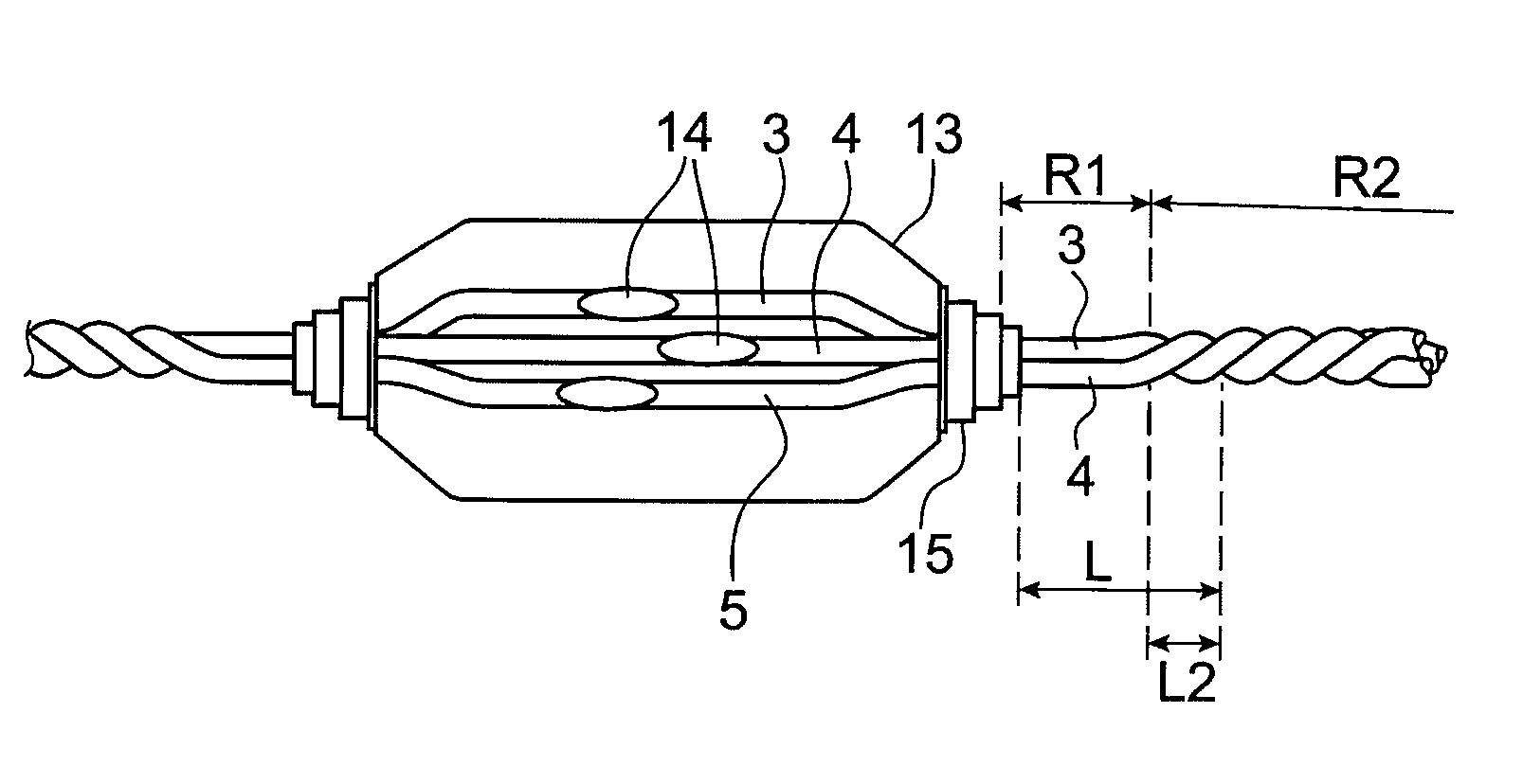
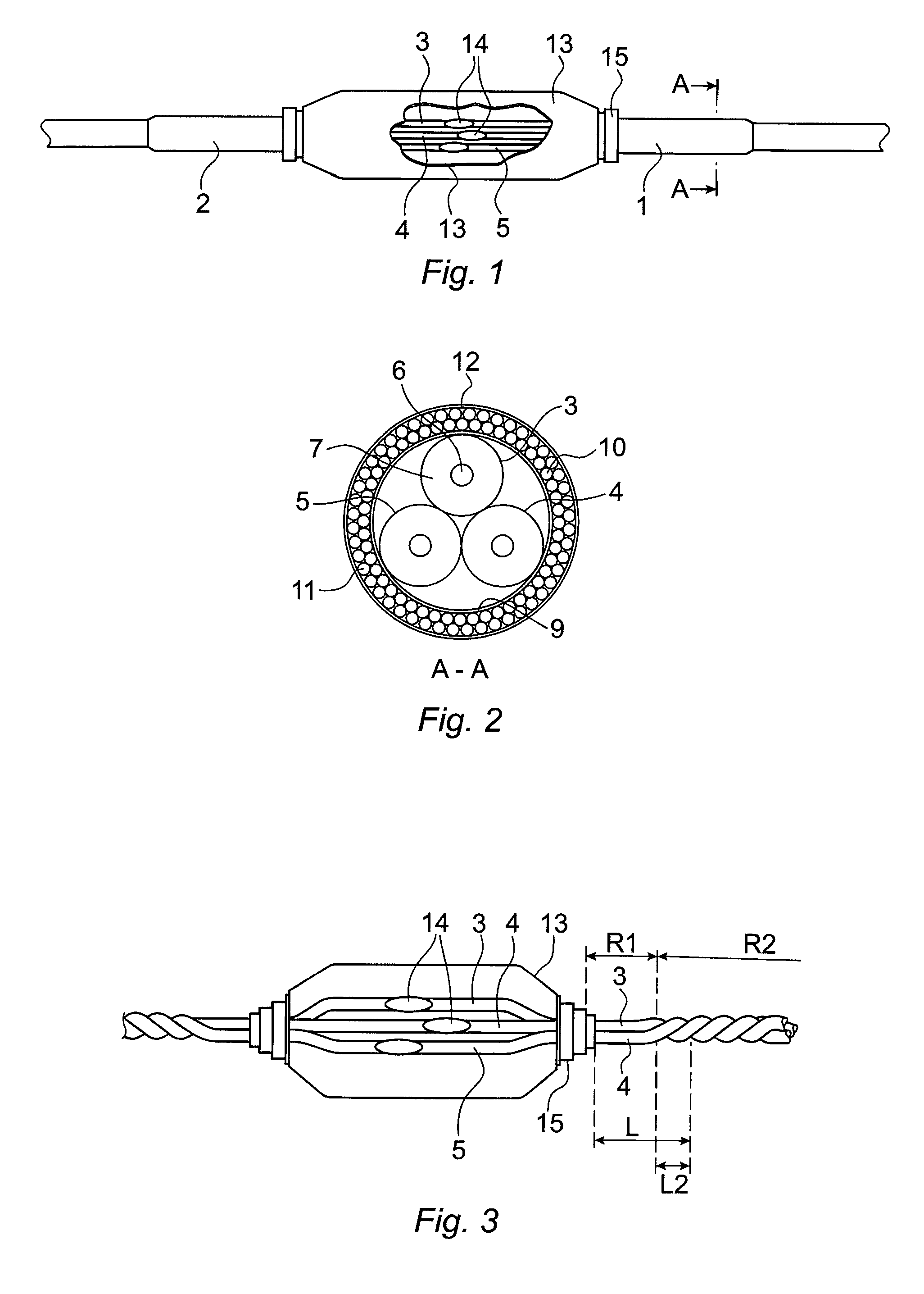
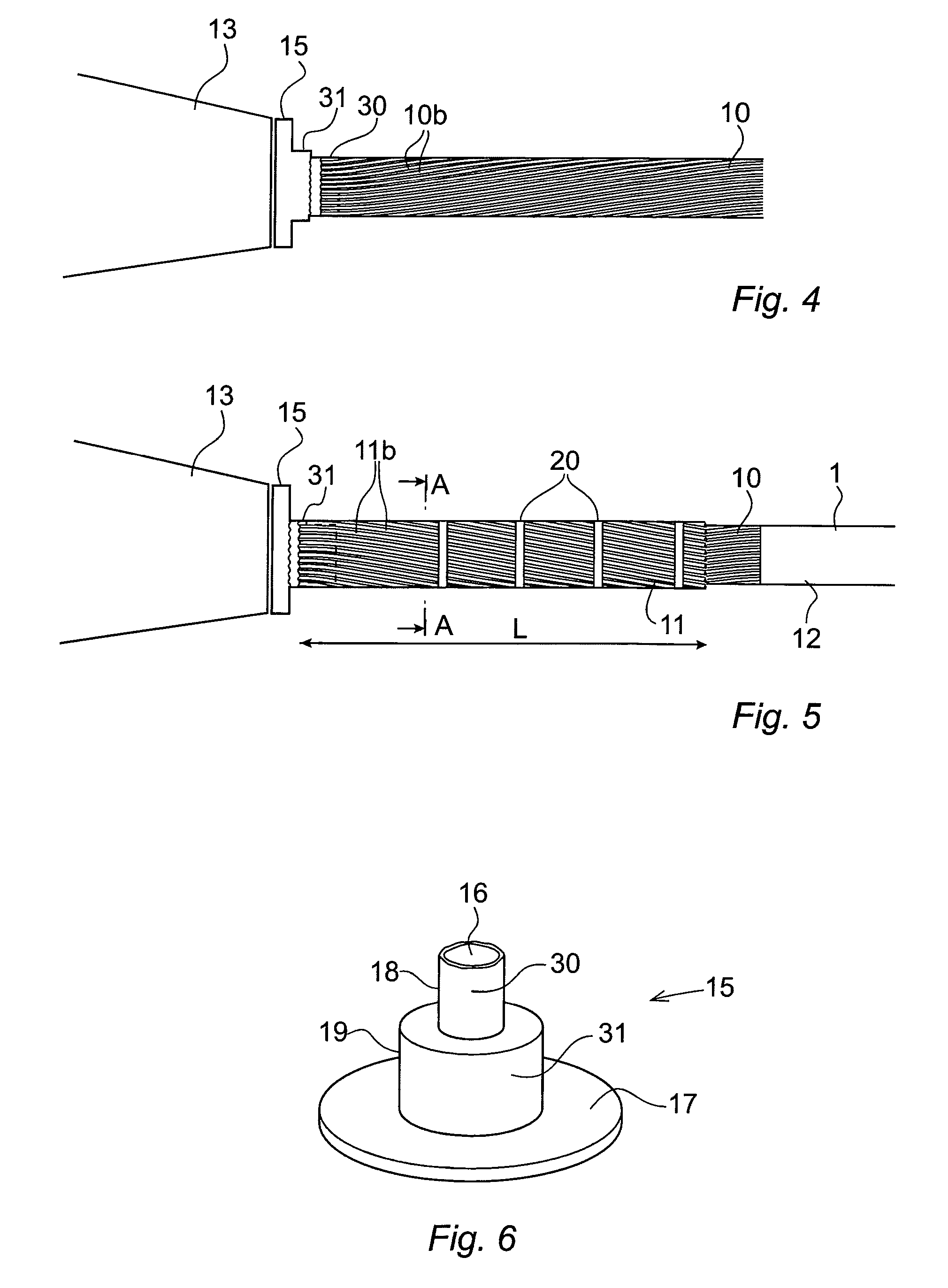
[0039]FIG. 1 shows a side view of a joint including two sections 1, 2 of an electric power cable according to an embodiment of the invention. FIG. 2 shows a cross section A-A of the cable section 1 shown in FIG. 1. The cable is a single armoured cable. Each cable section 1, 2 comprises at least one core member. In a DC cable, the cable section has one core member and in an AC cable, the cable section has tree core members. In the embodiment described in the following, sections of an AC power cable for submarine applications, having three core members 3, 4, 5, are joined together. Each cable core includes an elongated conductor 6 surrounded by an insulating layer 7 and an outer protective sheet acting as a water barrier. The three core members 3, 4, 5 are surrounded by a binder layer 9 that holds the cable cores together. The core members 3, 4, 5 and the binder layer 9 are surrounded by a first armoring layer 10 for protecting the core members from tensile forces acting on the cable....


PUM

PropertyMeasurementUnit
Lengthaaaaaaaaaa
Lengthaaaaaaaaaa
Distanceaaaaaaaaaa

Abstract

A joint including two sections of an electric power cable, each cable section including at least one core member surrounded by a first armouring layer for protecting the core member from tensile forces acting on the cable, the first armoring layer including a plurality of armoring wires arranged along the length of the cable and twisted in a first direction with respect to the longitudinal direction of the cable. The joint includes at least one core joint between the core members of the cable sections, and an outer mechanical casing surrounding the at least one core joint and mechanically connected to the first armoring layers of the cable sections, and a second armouring layer positioned in an area neighboring the casing, surrounding at least one of the cable sections, and having one end mechanically connected to the casing and the other end terminated at a distance from the casing.

Description

FIELD OF THE INVENTION[0001]The present invention relates to a joint including two sections of an electric power cable, each cable section comprising at least one core member surrounded by an armouring layer for protecting the core member from forces acting on the cable.[0002]The present invention also relates to a method for joining two sections of an electric power cable. The present invention also relates to use of the method according to the invention for joining three-phase sea cables. Particularly, the invention relates to a high voltage power cable. With high voltage is meant voltages above 1 kV.BACKGROUND OF THE INVENTION[0003]Electric power sea cables are laid down on the bottom of the sea and often extend a long distance. Due to the long distance, one or more cables must be joined together to provide a cable with a suitable length. The jointing of the cables is done onboard a ship during laying of the cable. Further, sometimes the cable has to be repaired and during the re...

Claims


Application Information

Patent Timeline
IPC IPC(8): H01B7/18H01B13/26H01B7/22H01B13/06H01B9/00H01B7/14
CPCH01B7/1875H01B9/00H01B13/26H01B7/226H01B13/06H01B7/14H02G1/14H02G15/117Y10T29/49195
Inventor ZETTERVALL, BJORN
Owner NKT HV CABLES AB
Why Eureka
Try Eureka