Resin molding die, resin molding method and resin molded product
What is AI technical title?
AI technical title is built by Patsnap AI team. It summarizes the technical point description of the patent document.
a resin molding and die technology, applied in the field resin molding methods, and resin molding products, can solve the problem that resin-molded products cannot be taken out of resin molding dies,
Active Publication Date: 2014-12-18
NEC PLATFORMS LTD
View PDF6 Cites 3 Cited by
Summary
Abstract
Description
Claims
Application Information
AI Technical Summary
This helps you quickly interpret patents by identifying the three key elements:
Problems solved by technology
Method used
Benefits of technology
Benefits of technology
The patent text describes a new type of resin molding die that can prevent burrs from occurring when there are undercuts on the core mold and embossing processes on the cavity mold. The technical effect of this new die is to improve the quality of the molded resin product and reduce the likelihood of defective parts being produced.
Problems solved by technology
However, when an uneven shape or a through hole that intersects with (is orthogonal to) the separating direction (mold removal direction) is formed on or in the resin-molded product, the resin-molded product cannot be taken out from the resin molding die as it is.
Method used
Image
Click on the blue label to locate the original text in one second.
Reading with bidirectional positioning of images and text.
Examples
first embodiment
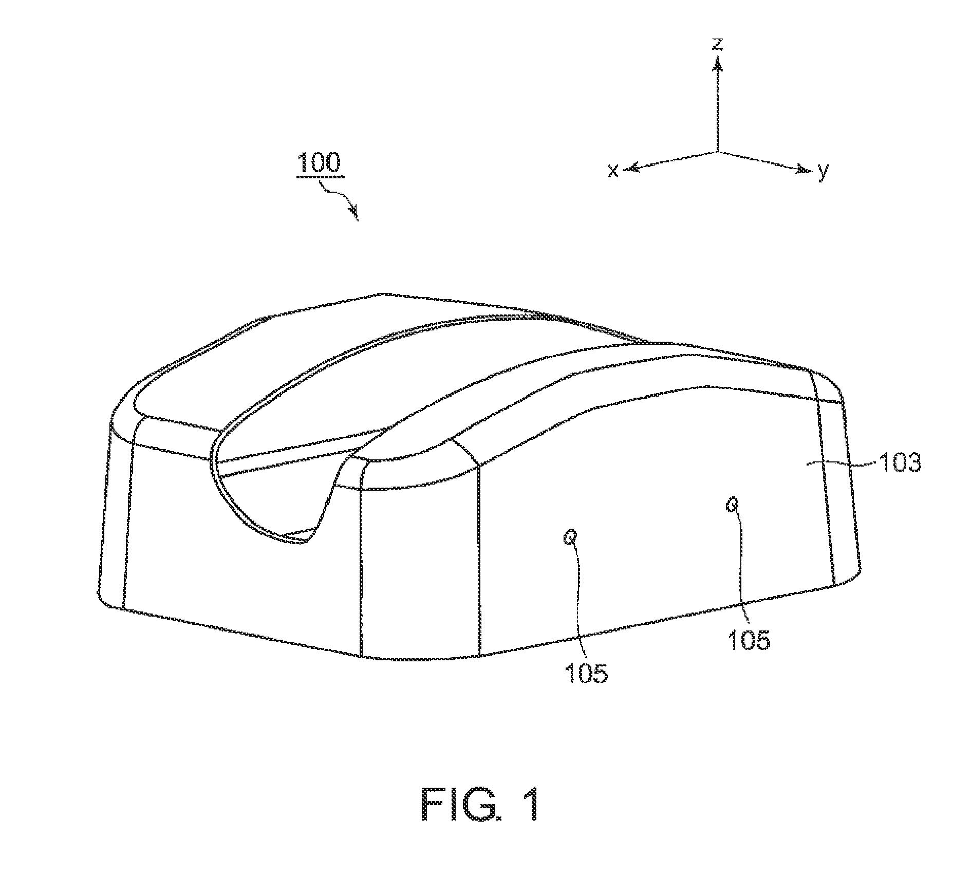
[0033]First, with reference to FIGS. 1 to 4, the configuration of a resin-molded product 100 that is molded using a resin molding die 1 according to this invention is described in brief.
[0034]In this case, as the resin-molded product 100, an outer frame to be used for a battery charger of a router is exemplified.
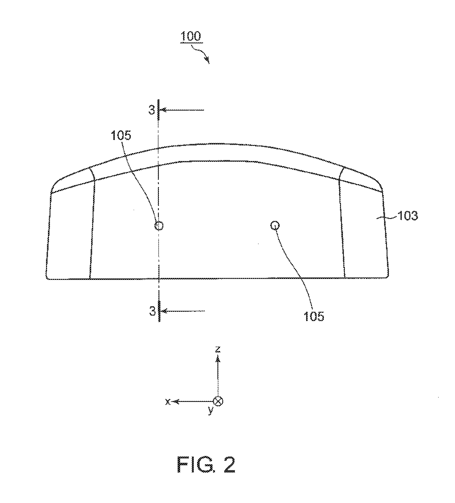
[0035]As illustrated in FIGS. 1 to 4, the resin-molded product 100 comprises a hollow box shape with an open bottom surface, and one of side surfaces 103 comprises through holes 105 formed therein.
[0036]As illustrated in FIG. 4, the through hole 105 comprises a tapered portion 105a radially expanded on an inner side of the side surface 103, and as described later, at the time of resin molding, the tapered portion 105a intersects with (is orthogonal to) a mold removal direction of the resin molding die 1.
[0037]Therefore, when the resin-molded product 100 is molded, the through hole 105 is an undercut, and the undercut needs to be provided on a core mold.
[0038]Note that, the t...
second embodiment
[0071]Next, this invention is described with reference to FIG. 13.
[0072]In the second embodiment, a fitting structure is provided to four corners of each of the core mold 4 and the cavity mold 5 of the first embodiment.
[0073]Note that, in the second embodiment, components having the same functions as those of the first embodiment are denoted by the same reference symbols, and parts different from those of the first embodiment are mainly described.
[0074]As illustrated in FIG. 13, a resin molding die 1a according to the second embodiment includes a core mold 4a and a cavity mold 5a each comprising a rectangular shape in plan view.
[0075]First positioning portions 41a, 41b, 41c, and 41d are provided on four corners of the core mold 4a, respectively, and second positioning portions 43a, 43b, 43c, and 43d are provided on four corners of the cavity mold 5a, respectively. The second positioning portions 43a to 43d have shapes corresponding to those of the first positioning portions 41a to 4...
PUM
Property
Measurement
Unit
Hardness
aaaaa
aaaaa
Abstract
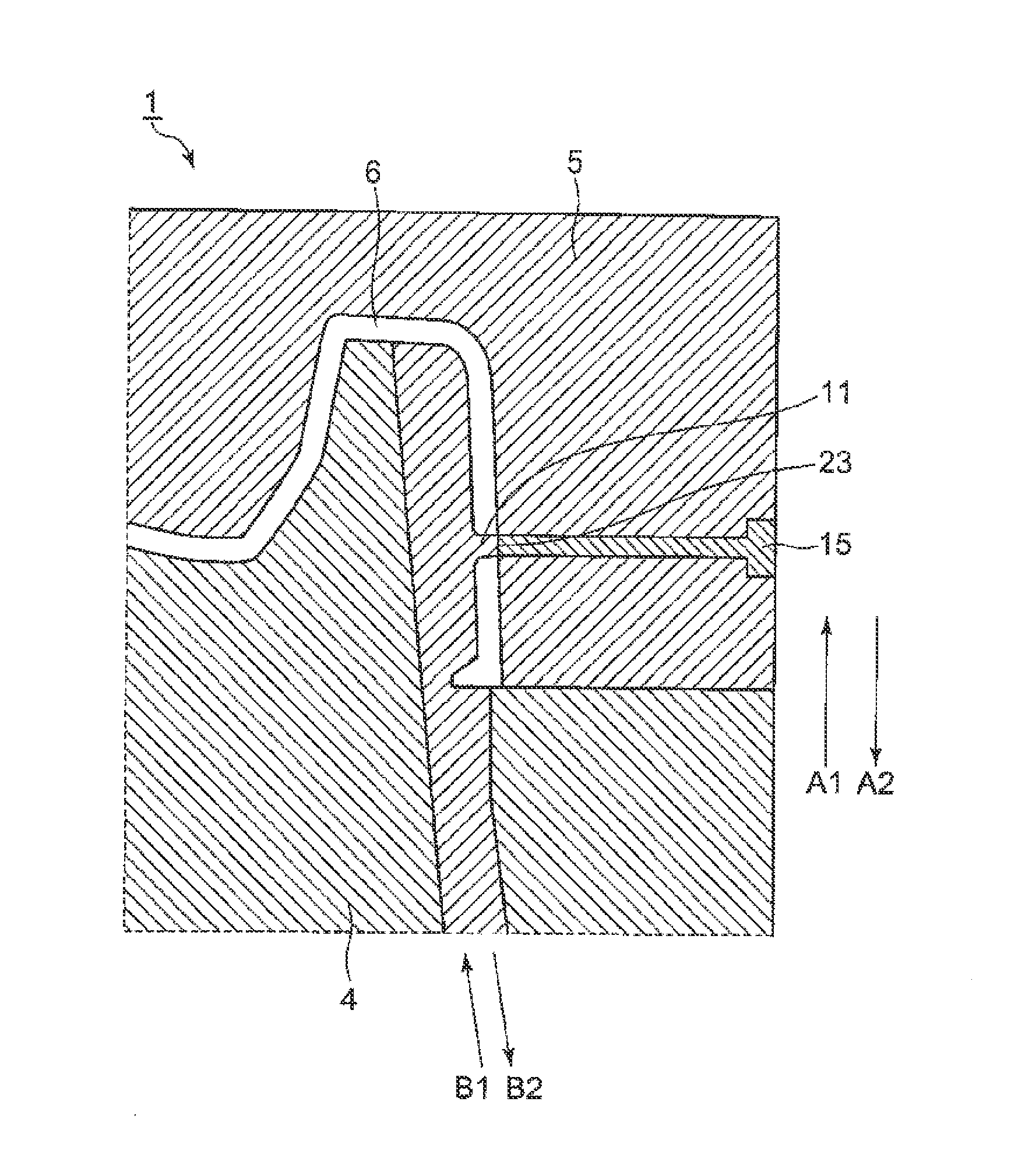
It is an object of this invention to provide a resin molding die that is capable of suppressing, even when an undercut is provided on a core mold and an embossing process is performed on a cavity mold, generation of burrs attributed to the undercut and the embossing process. A resin molding die (1) of this invention includes: a core mold (4) including a protrusion (11) formed on a surface thereof as an undercut, the protrusion (11) being provided so as to form a through hole (105) in a resin-molded product (100); and a cavity mold (5) provided so as to be engageable with the core mold (4). The cavity mold (5) includes: a cavity main body (13) including an embossed surface that is opposed to the surface of the core mold (4), on which the protrusion (11) in provided, under a state in which the cavity mold (5) and the core mold (4) are engaged with each other; and an insert (15) provided to the cavity main body (13) so as to abut on the protrusion (11), the insert (15) including a mirror-finished surface as an opposing surface (23) thereof that abuts on the protrusion (11).
Description
TECHNICAL FIELD[0001]This invention relates to a resin molding die, a resin molding method, and a resin-molded product.BACKGROUND ART[0002]A resin molding die includes a core mold generally having a shape corresponding to an inner surface of a resin-molded product and a cavity mold provided so as to be engageable with the core mold and generally having a shape corresponding to an outer surface of the resin-molded product.[0003]In such a resin molding die, a space (cavity), which is formed under a state in which the core mold and the cavity mold are engaged with each other, has a shape corresponding to the resin-molded product, and a molten resin is injected into the cavity to be cured. In this manner, the resin-molded product is manufactured (Patent Literatures 1 and 2).[0004]In this case, after the resin is cured, it is necessary to separate the core mold and the cavity mold to take out the resin-molded product from the resin molding die. However, when an uneven shape or a through ...
Claims
Application Information
Patent Timeline
Application Date:The date an application was filed.
Publication Date:The date a patent or application was officially published.
First Publication Date:The earliest publication date of a patent with the same application number.
Issue Date:Publication date of the patent grant document.
PCT Entry Date:The Entry date of PCT National Phase.
Estimated Expiry Date:The statutory expiry date of a patent right according to the Patent Law, and it is the longest term of protection that the patent right can achieve without the termination of the patent right due to other reasons(Term extension factor has been taken into account ).
Invalid Date:Actual expiry date is based on effective date or publication date of legal transaction data of invalid patent.

