
Measurement and System for Performing a Calibration

a technology of measurement and calibration, applied in the direction of resistance/reactance/impedence, instruments, and monitoring of receivers, etc., can solve the problems of imperfect operation of the receiver device operating at rf and microwave frequencies

Active Publication Date: 2014-12-18
NAT INSTR IRELAND RESOURCES
View PDF14 Cites 12 Cited by
  • Summary
  • Abstract
  • Description
  • Claims
  • Application Information

AI Technical Summary

Benefits of technology

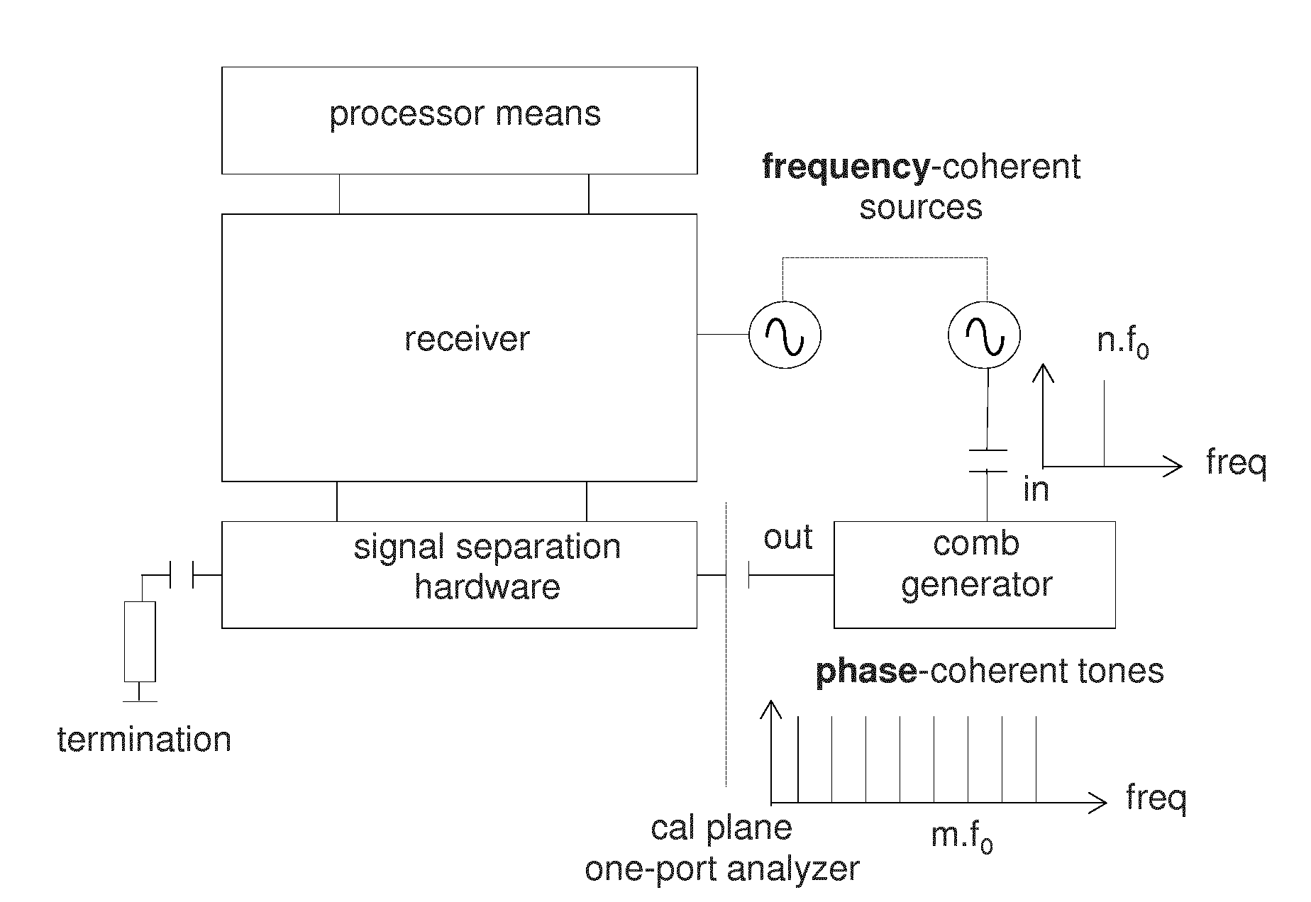
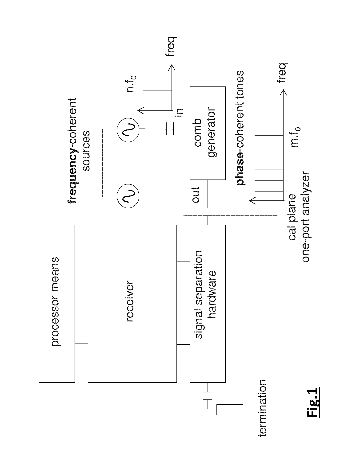
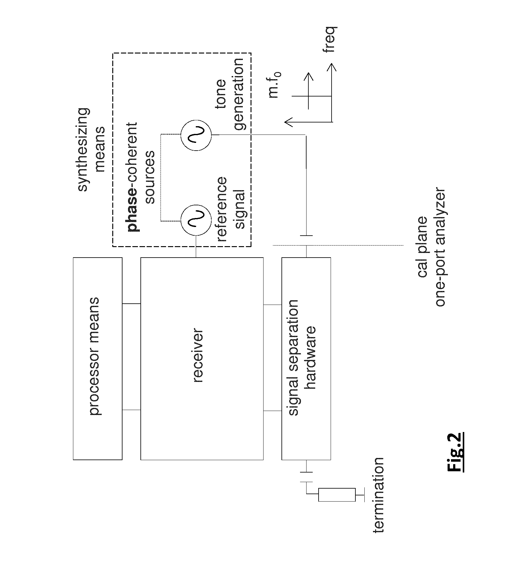
The present invention provides a method and system for calibrating a receiver device or a stimulus-response system comprising a receiver device without the need for a separate pulse generator or phase-coherent multi-tone generator. The calibration process involves applying and measuring at least one tone in a phase-coherent way, which enables repeatable phase relationships between different calibration tones. The method has various advantages, such as not requiring expensive additional hardware and automatically covering the frequency range of the stimulus-response system. Additionally, there is no typical roll-off with increasing frequency of the amplitude spectrum of a calibrated pulse generator.

Problems solved by technology

A receiver device operating at RF and microwave frequencies is not perfect.

Method used


Image

  • Measurement and System for Performing a Calibration
  • Measurement and System for Performing a Calibration
  • Measurement and System for Performing a Calibration

Examples


Embodiment Construction

[0037]The present invention will be described with respect to particular embodiments and with reference to certain drawings but the invention is not limited thereto but only by the claims.

[0038]Furthermore, the terms first, second and the like in the description and in the claims, are used for distinguishing between similar elements and not necessarily for describing a sequence, either temporally, spatially, in ranking or in any other manner. It is to be understood that the terms so used are interchangeable under appropriate circumstances and that the embodiments of the invention described herein are capable of operation in other sequences than described or illustrated herein.

[0039]It is to be noticed that the term “comprising”, used in the claims, should not be interpreted as being restricted to the means listed thereafter; it does not exclude other elements or steps. It is thus to be interpreted as specifying the presence of the stated features, integers, steps or components as re...


PUM


Abstract

The present invention relates to a method for calibrating a receiver device or a stimulus-response system comprising a receiver device. The method comprises the steps ofgenerating at least one tone with a repeatable and known phase value, said at least one tone being stepped in frequency to cover a given set of calibration tones, and applying the at least one tone to the receiver device or to the stimulus-response system,generating a reference signal, which is phase-coherent with the at least one tone, to measure in a phase-coherent way with the receiver device or with the stimulus-response system the at least one tone,measuring at least the phase of the at least one tone using the receiver device or the stimulus-response system,determining at least phase-related information for calibration coefficients at the given set of calibration tones by calculating a phase deviation of the measured phase from the known phase value of the at least one tone.

Description

FIELD OF THE INVENTION [0001]The present invention is generally related to the field of radio frequency (RF) and microwave measurement technology. More in particular, it relates to calibration techniques for receivers and stimulus-response systems so that a signal and a device under test, respectively, can be characterized in an accurate way.BACKGROUND OF THE INVENTION[0002]A receiver device operating at RF and microwave frequencies is not perfect. For instance the frequency response of its input channels is not ideal: the amplitude varies as function of frequency and the phase is not perfectly linear as a function of frequency. Also, the input impedance of these channels deviates from the nominal value (typically, but not necessarily 50 Ohm). In order to perform accurate measurements of unknown signals, such receiver device has to be calibrated by applying an appropriate well known signal at one or more input channels. Comparing the signal as measured by the receiver device to the ...

Claims


Application Information

Patent Timeline
Patent Type & Authority Applications(United States)
IPC IPC(8): G01R25/00G01R35/00
CPCG01R35/005G01R25/00H04B17/21G01N27/64G01R23/00G01R27/02
Inventor PAILLONCY, GUILLAUMEVANDEN BOSSCHE, MARCVERBEYST, FRANS
Owner NAT INSTR IRELAND RESOURCES
Learn More