Electrical circuit for delivering power to consumer electronic devices

a technology of electric circuits and electronic devices, applied in the direction of electric variable regulation, process and machine control, instruments, etc., can solve the problems of not doing anything, wasting electricity, devices and appliances continuing to draw current, adding to the energy crisis worldwide, and costing you money

Active Publication Date: 2014-12-18
SMART PRONG TECH INC
View PDF37 Cites 15 Cited by
  • Summary
  • Abstract
  • Description
  • Claims
  • Application Information

AI Technical Summary

Benefits of technology

[0031]In another aspect of the present invention, an electrical circuit for providing electrical power for use in charging applications and/or powering a constant supply circuit for electronic devices is provided. The electrical circuit includes a power converter circuit electrically that is coupled to an electrical power source for receiving alternating current (AC) input power from the electrical source and delivering direct current (DC) output power to an electronic device. The power converter circuit includes a transformer and a switching device coupled to a primary side of

Problems solved by technology

All this means that even when a cell phone, lap top or like device is completely charged, current is still flowing, but not accomplishing anything and wasting electricity.
Most recently manufactured devices and appliances continue to draw current all day, every day—and cost you money and add to the Energy Crisis Worldwide.
“The impact of plug loads on overall consumption is quite significant.
One of the problems experienced by virtually all modern electronics is that power supplies, whether external or embedded “power modules” are not energy efficient.
Transformers are inherently inefficient because, as an analog device, they can only produce on power output for each specific winding.
Moreover, there are often over 50 parts and pieces that are necessary to work with a transformer to create a common modern external power supply, the numbers only get somewhat lower with internal or embedded power modules.
The number of parts in a power supply is inherently inefficient because current must travel in, around and through the various parts, each with different powe

Method used


Image

  • Electrical circuit for delivering power to consumer electronic devices
  • Electrical circuit for delivering power to consumer electronic devices
  • Electrical circuit for delivering power to consumer electronic devices

Examples


Embodiment Construction

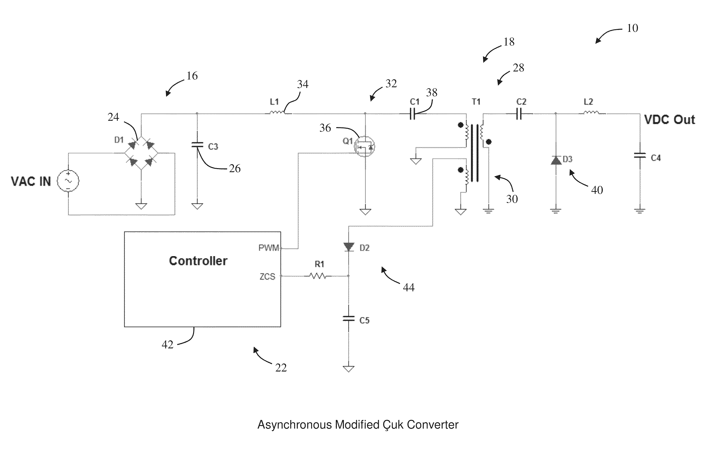
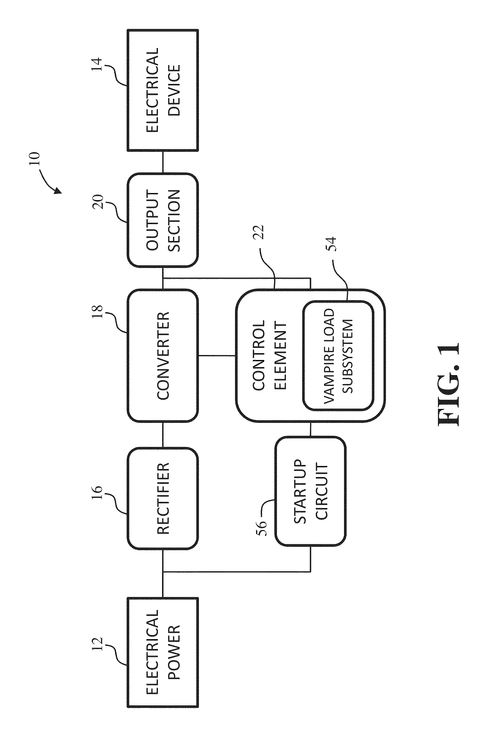
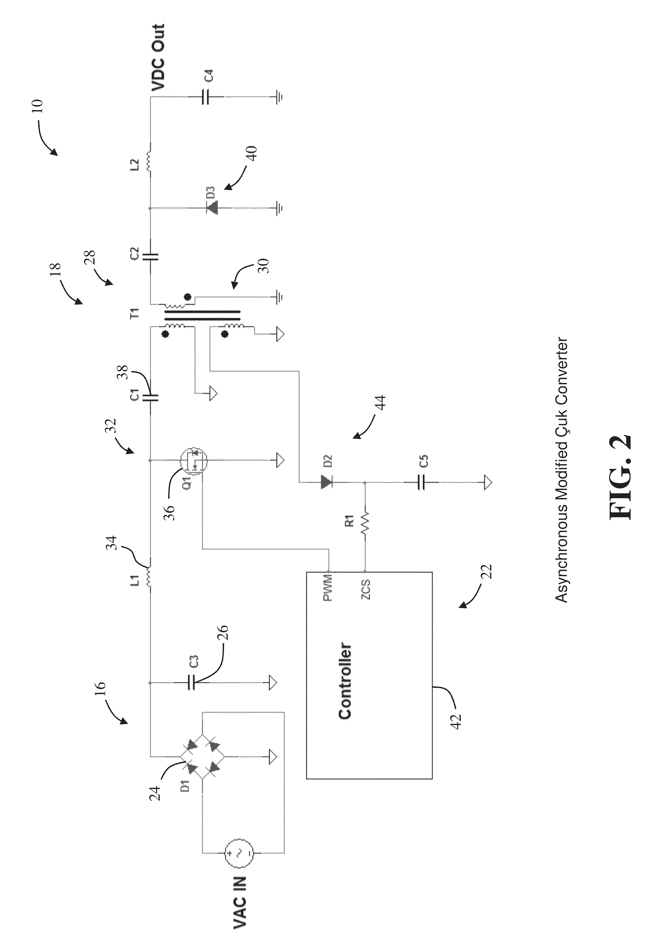
[0053]With reference to the drawings and in operation, the present invention overcomes at least some of the disadvantages of known power delivery systems by providing a power circuit that provides DC voltage output power to consumer electronic devices from an AC mains supply (typically 120 VAC (US) to 264 VAC[EU / Asia]). The power circuit is configured to provide electrical power to charge electronic storage devices and / or power consumer electronic products. The power circuit includes a power converter circuit that includes a switching device connected to the primary side of a transformer and a controller that is coupled to the switching device to adjust the duty cycle of the switching device to adjust a voltage level of the output power to within a desired power specification. In addition, the controller may adjust the frequency of the switching device to adjust a voltage level of the output power. By providing a switching device such as, for example a MOSFET, connected to the prima...


PUM


Abstract

An electrical circuit for providing electrical power for use in powering electronic devices is described herein. The electrical circuit includes a power converter circuit that is electrically coupled to an electrical power source for receiving alternating current (AC) input power from the electrical source and delivering direct current (DC) output power to an electronic device. The power converter circuit includes a transformer and a switching device coupled to a primary side of the transformer for delivering power from the electrical power source to a primary side of the transformer. A controller is coupled to a voltage sensor and the switching device for receiving the sensed voltage level from the voltage sensor and transmitting a control signal to the switching device to adjust the voltage level of power being delivered to the electronic device.

Description

CROSS-REFERENCES TO RELATED APPLICATIONS[0001]This application claims the benefit of U.S. Provisional Patent Application Ser. No. 61 / 844,784, filed on Jul. 10, 2013, claims the benefit of U.S. Provisional Patent Application Ser. No. 61 / 841,079, filed on Jun. 28, 2013, and claims the benefit of U.S. Provisional Patent Application Ser. No. 61 / 835,438, filed on Jun. 14, 2013, all of which are hereby incorporated by reference in their entirety for all purposes.FIELD OF THE INVENTION[0002]The present invention relates generally to electrical power circuits and, and more particularly, to an electrical power circuit for providing electrical power for use in charging consumer electronic devices.BACKGROUND OF THE INVENTION[0003]The Energy Crises Requires Demand Side Response That Lowers Current Loads. The Energy Crisis is upon us worldwide. For instance, the U. S. Department of Energy predicts that by 2015 there will not, on the average, be enough electric power to supply average demand in t...

Claims


Application Information

Patent Timeline
IPC IPC(8): H02M3/335H02M1/00
CPCH02M3/335H02M3/33592H02M3/005H02M3/073H02M3/33569H02M3/3376H02M3/33523Y02B70/10H02M1/0006H02M1/0032H02M1/0058H02M3/1557H02M3/01H02M1/0009H02M1/0054H02M1/08H02M1/36H02M3/33507
Inventor FREEMAN, MICHAEL H.DIETER, ROBERTFREEMAN, MITCHAEL C.PILLAI, SATEESHSEGARRA, DANIEL
Owner SMART PRONG TECH INC
Why Eureka
Try Eureka