
Radiation generating tube, and radiation generating apparatus and radiation imaging system using the same

a radiation generating apparatus and radiation imaging technology, applied in vacuum tube vessels/containers/shields, instruments, nuclear engineering, etc., can solve the problems of thermal stress caused by the difference in linear expansion coefficient, rapid increase in temperature of anodes, and increased thermal stress caused by linear expansion coefficients. achieve the effect of high resolution

Active Publication Date: 2014-12-18
CANON KK
View PDF6 Cites 8 Cited by
  • Summary
  • Abstract
  • Description
  • Claims
  • Application Information

AI Technical Summary

Benefits of technology

The present invention is about a new kind of tube used in radiation generators. It was made to prevent damage to the insulating tube caused by heat generated during operation. The invention also includes a radiation imaging system that uses this special tube and can capture high-quality images.

Problems solved by technology

However, a rapid increase in temperature of the anode is not sufficiently handled by the temperature equalization by the insulating fluid in some cases.
Therefore, in the case where the temperature of the anode and the insulating tube increases, thermal stress is caused due to the difference in linear expansion coefficient.
Further, as described above, in the case where the anode increases in temperature rapidly, a temperature difference between the anode and the insulating tube is widened, and the thermal stress caused by the difference in linear expansion coefficient further increases, with the result that the joint portion between the insulating tube and the anode is subjected to damage such as cracks in some cases.
Such damage to the insulating tube lowers the vacuum degree of the vacuum container, which is one cause for impairing the reliability of the radiation generating apparatus.
As a result, in the same way as in the anode, thermal stress is concentrated on the periphery of a joint portion between the insulating tube and the cathode, and the insulating tube is subjected to damage such as cracks in some cases.

Method used


Image

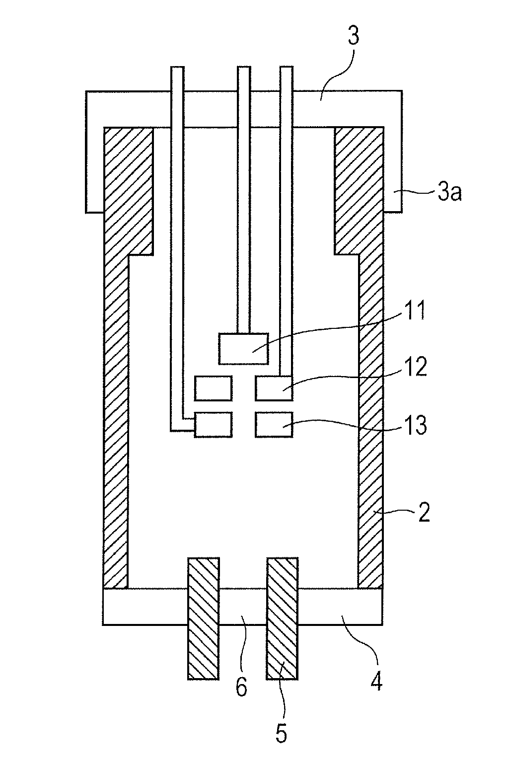
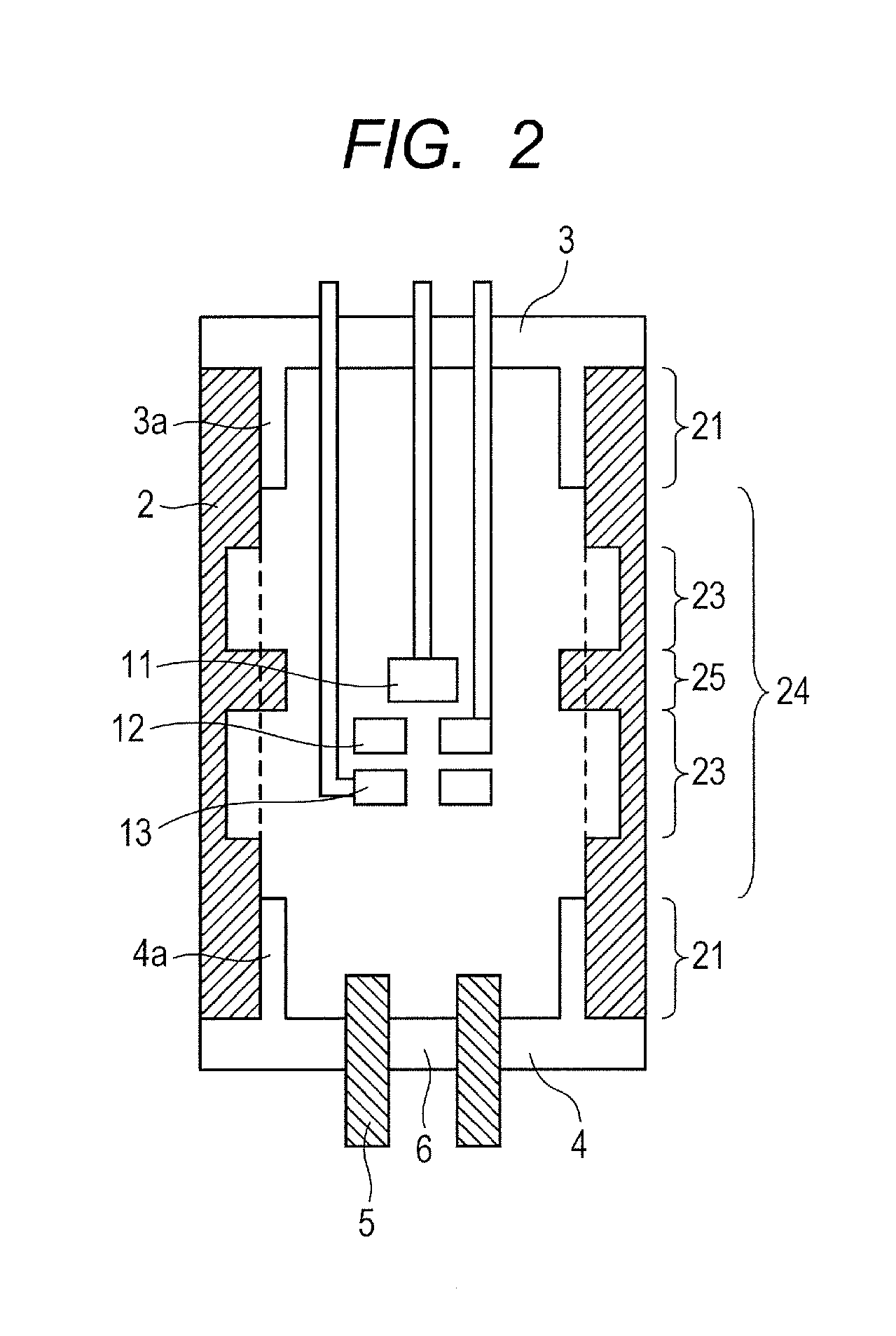
  • Radiation generating tube, and radiation generating apparatus and radiation imaging system using the same
  • Radiation generating tube, and radiation generating apparatus and radiation imaging system using the same
  • Radiation generating tube, and radiation generating apparatus and radiation imaging system using the same

Examples


example 1

[0051]The radiation generating apparatus illustrated in FIG. 5 including the radiation generating tube 1 having a schematic configuration illustrated in FIG. 7A was produced.

[0052]As the insulating tube 2, a cylindrical insulating tube made of alumina having a length of 80 mm, an outer periphery diameter of 50 mm, an inner periphery diameter in a thicker tube wall portion of 40 mm, and an inner periphery diameter in a thinner tube wall portion of 44 mm was used. The tube wall thickness of the thicker tube wall portion was 5 mm, and the tube wall thickness of the thinner tube wall portion was 3 mm. The thicker tube wall portion of the insulating tube 2 was formed to extend in a range of 11 mm from the one of the pair of openings toward the other of the pair of openings. A region extending from a position of 11 mm from one of the pair of openings to a position of 23 mm therefrom toward the other of the pair of openings was formed as a tube wall thickness changing region between the th...

example 2

[0059]As illustrated in FIG. 7B, a radiation generating apparatus was produced in the same way as in Example 1 with the exception that the shapes of the cathode 3 and the anode 4 and the position of the thicker tube wall region of the insulating tube 2 were opposite to those of Example 1.

[0060]In this example, an increase in temperature of the anode 4 caused by the heat generation of the target 6 is transmitted to the insulating tube 2, and thermal stress is concentrated on a joint portion between the insulating tube 2 and the anode 4. However, also in this example, the insulating tube 2 is deformed in the thinner tube wall region to alleviate the concentration of thermal stress on the joint portion, and a decrease in vacuum degree of the radiation generating tube 1 to be caused by the damage such as cracks of the insulating tube 2 can be prevented.

example 3

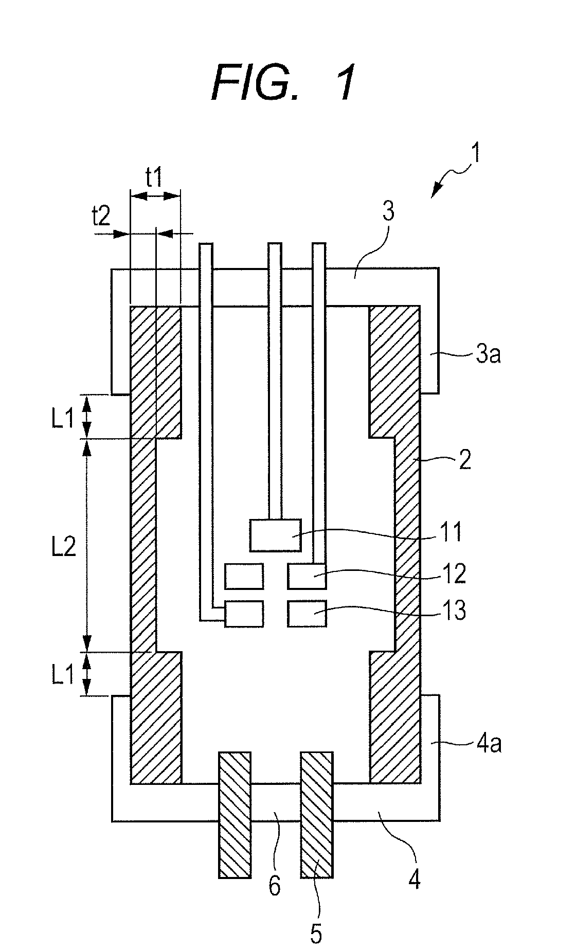
[0061]A radiation generating apparatus was produced in the same way as in Examples 1 and 2 with the exception that the radiation generating tube as illustrated in FIG. 1 was obtained by combining Examples 1 and 2.

[0062]In this example, the concentration of thermal stress in the joint portions of the insulating tube 2 with respect to the cathode 3 and the anode 4 caused by an increase in temperature of both the cathode 3 and the anode 4 can be alleviated, and a decrease in vacuum degree of the radiation generating tube 1 to be caused by damage such as cracks of the insulating tube 2 can be prevented.

[0063]According to the present invention, the extending portion is provided to at least one of the anode and the cathode to join the extending portion to the insulating tube, to thereby increase the strength of the joint portion. Further, a thinner tube wall region is provided in the intermediate portion in the longitudinal direction of the insulating tube, and thus thermal stress concent...


PUM

PropertyMeasurementUnit
diameteraaaaaaaaaa
diameteraaaaaaaaaa
lengthaaaaaaaaaa

Abstract

Provided is a radiation generating tube in which an insulating tube is prevented from being damaged by heat generation of a target or an electron emitting source during drive. Extending portions extending along an outer periphery of an insulating tube are provided to a cathode and an anode, respectively, and the insulating tube is joined to the extending portions to enhance the strength of joint portions. At the same time, the insulating tube can be deformed easily by setting a tube wall thickness of the insulating tube at a central portion in a longitudinal direction to be smaller than a tube wall thickness of an opening end, and thus the concentration of thermal stress on the joint portions caused by an increase in temperature of the cathode and the anode is alleviated.

Description

BACKGROUND OF THE INVENTION[0001]1. Field of the Invention[0002]The present invention relates to a radiation generating tube, and a radiation generating apparatus and a radiation imaging system including the radiation generating tube, which can be used for a medical equipment, a nondestructive inspection apparatus, and the like, for example.[0003]2. Description of the Related Art[0004]In general, a radiation generating apparatus includes a radiation generating tube as a radiation source. The radiation generating tube includes a vacuum container in which a cathode is mounted to one opening of an insulating tube and an anode is mounted to the other of the pair of openings thereof. An electron emitting source is connected to the cathode, and the anode includes a target. The radiation generating tube irradiates the target with an electron emitted from the electron emitting source by applying a high voltage between the cathode and the anode, and thus generates a radiation such as an X-ra...

Claims


Application Information

Patent Timeline
Patent Type & Authority Applications(United States)
IPC IPC(8): H01J35/16H01J35/06H01J35/08G01N23/04
CPCH01J35/16H01J35/08H01J35/06G01N23/04H01J19/42H01J19/56H01J2235/166H05G1/06H01J35/116G21G4/08H01J37/16H01J2229/4827H01J2229/86H01J2235/16H01J2235/165H01J2237/16H05G1/04
Inventor UKIYO, NORITAKASATO, YASUEYANAGISAWA, YOSHIHIROSANDO, KAZUHIRO
Owner CANON KK
Learn More