

Stretch Valve Balloon Catheter and Methods for Producing and Using Same
- Summary
- Abstract
- Description
- Claims
- Application Information
AI Technical Summary
Benefits of technology
Problems solved by technology
Method used
Image

Examples
first embodiment
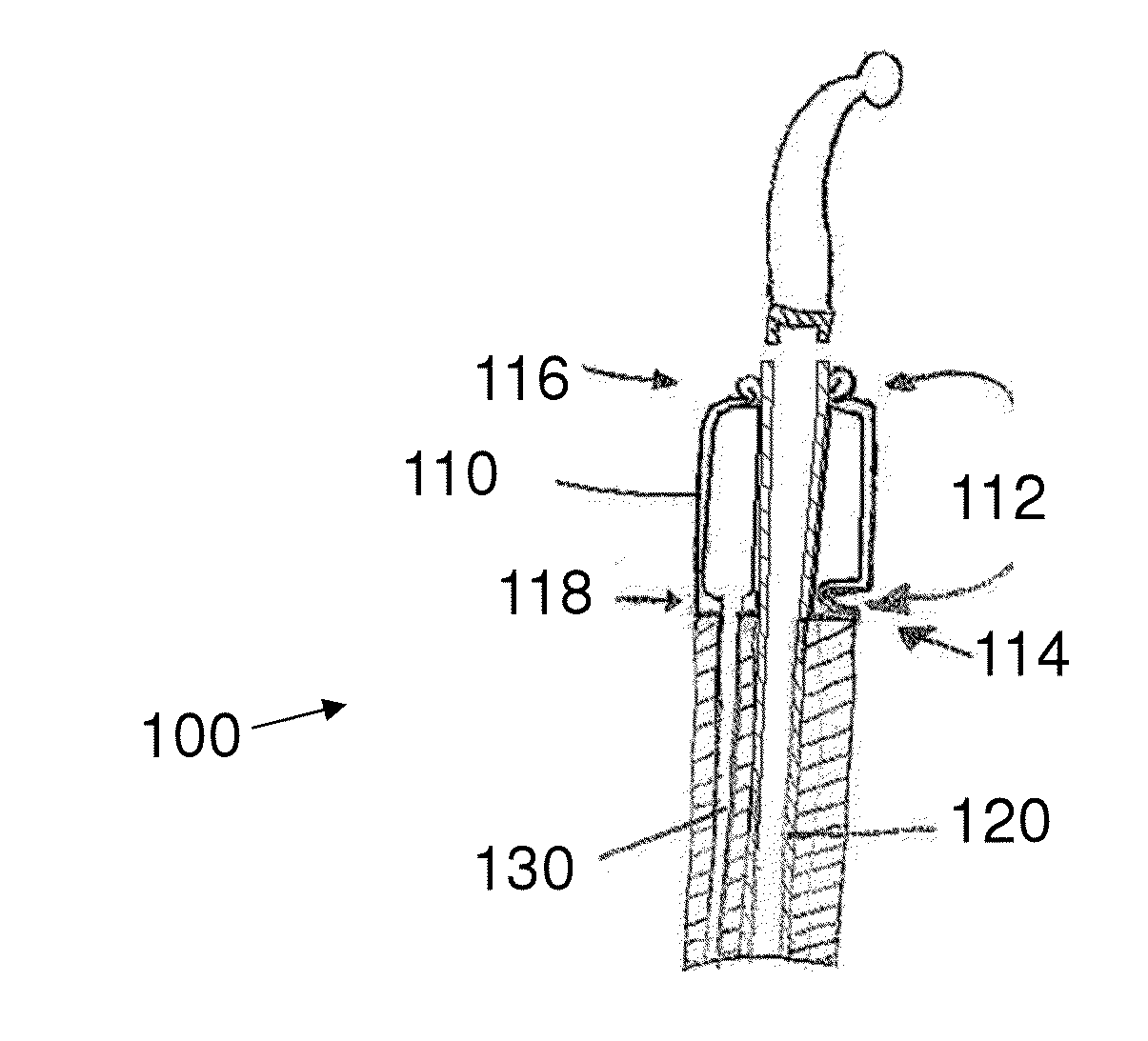
[0130]Referring now to the figures of the drawings in detail and first, particularly to FIG. 2 thereof, there is shown a pressure-limiting balloon catheter 100 that does not inflate past the tearing limit of a lumen in which the catheter 100 is placed, for example, in the urethra.
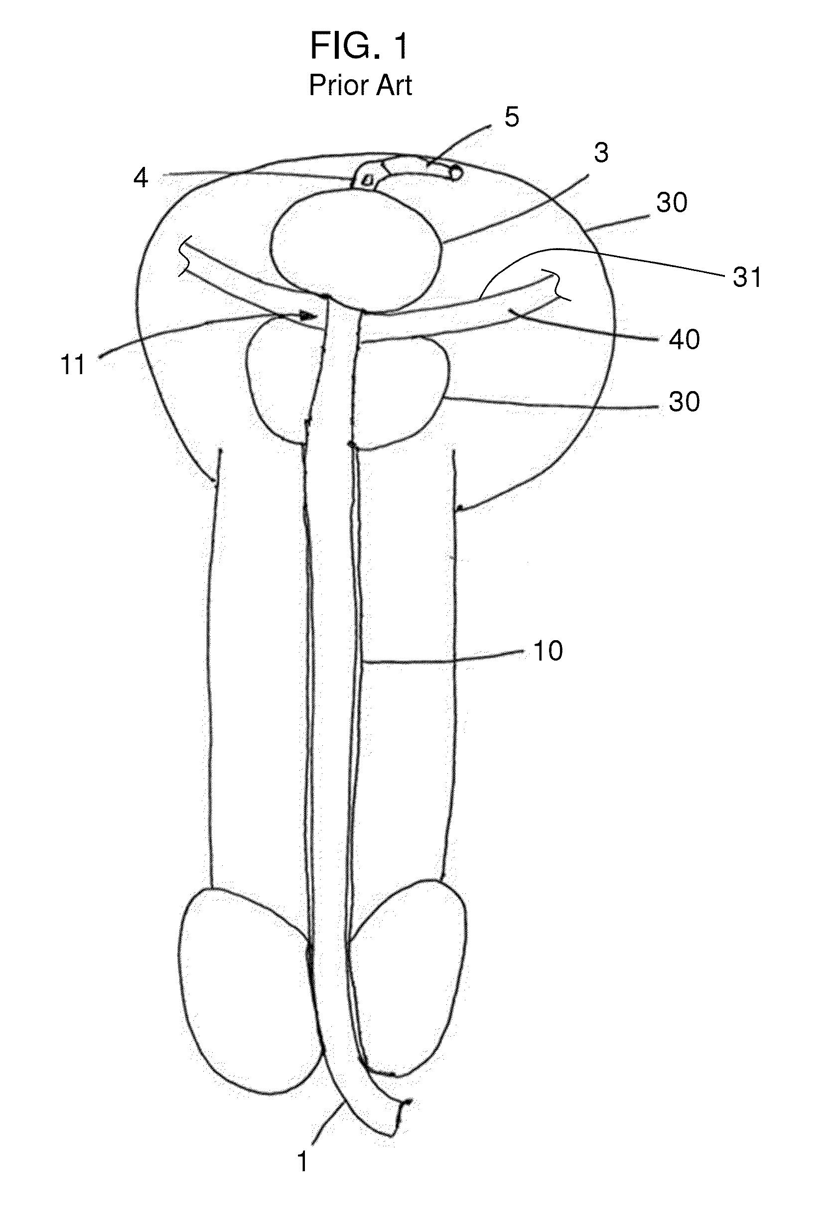
[0131]To prevent occurrences of urethra tearing due to premature-improper inflation of the balloon and / or due to premature removal of an inflated balloon, the invention of the instant application provides the balloon 110 with a balloon safety valve 112. As set forth above, in a balloon 3 of a conventional catheter (see reference numerals 1 to 5 in FIG. 1), the high-pressure balloon 3 is fixed to the outer surface of the fluid drainage lumen 120 (not shown in FIG. 1) and is not intended to be removed therefrom or to burst thereon unless an extraordinary amount of inflation occurs. Such a tearing event is not supposed to occur under any circumstances during use with a patient. If such an event happens, the ma...
second embodiment
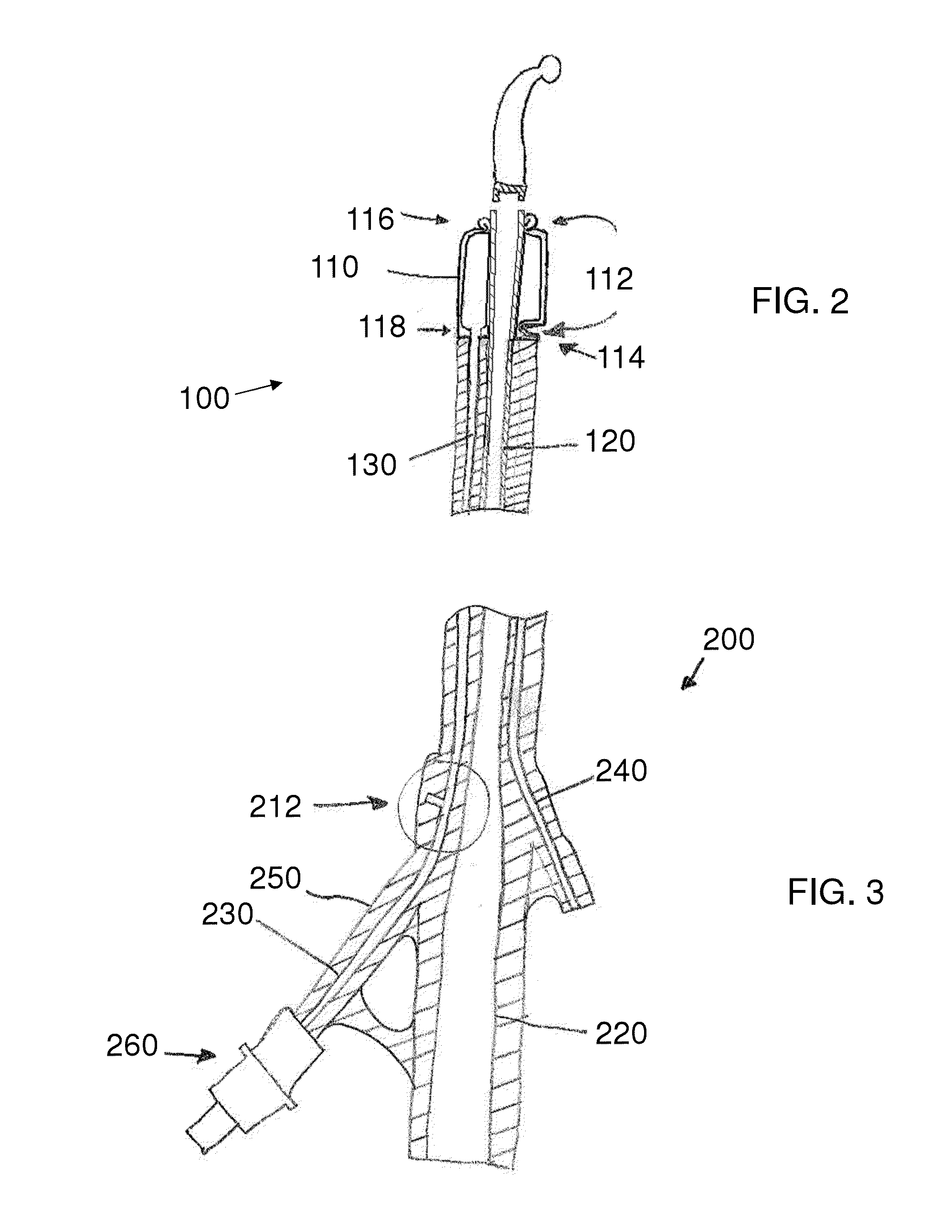
[0137]the one-use breaking safety valve of a pressure-limiting balloon catheter 200 is shown in FIG. 3. The catheter 200 has a fluid drainage lumen 220, a balloon inflation lumen 230, and a secondary lumen 240.
[0138]The fluid drainage lumen 220 is connected fluidically to the body cavity (i.e., the bladder 30) for draining fluid from the body cavity.
[0139]The secondary lumen 240 can be used for any purpose, for example, for housing the radiation line that will supply energy to the radiation coil 2. It can also be used for injecting fluid into any distal part of the catheter 200 or even the body cavity itself.
[0140]The balloon inflation lumen 230 begins at a proximal end with an inflating connector 260 that, in an exemplary embodiment, is one part of a luer connector. The balloon inflation lumen 230 continues through the body of the catheter 200 all the way to the balloon 110 and is fluidically connected to the interior of the balloon 110.
[0141]Alternatively or additionally, the ball...
PUM
 Abstract
Description
Claims
Application Information