Method and device for manufacturing film-wrapped electrical device

a technology of electrical devices and film wraps, which is applied in the manufacture of electrolytic capacitors, cell components, cell component details, etc., can solve the problems of extremely poor production efficiency, extremely low rate of impregnation with electrolyte solution, and time-consuming to impregnate the gaps in the electrode assembly with electrolyte solution

Active Publication Date: 2014-12-25
AUTOMOTIVE ENERGY SUPPLY +1
View PDF6 Cites 14 Cited by
  • Summary
  • Abstract
  • Description
  • Claims
  • Application Information

AI Technical Summary

Benefits of technology

[0013]In view of this, an object of the present invention is to provide a method and a device for manufacturing a film-wrapped electrical device with which an electrode assembly is less likely to be unevenly impregnated with electrolyte solution, and the electrolyte solution can be injected within a short period of time.

Problems solved by technology

However, since the electrode assembly is usually obtained by tightly stacking electrode plates, it takes time to impregnate the gaps in the electrode assembly with the electrolyte solution.
For the standing electrolyte solution to naturally permeate the gaps between the electrodes, it is necessary to leave them, for example, a whole day and night, and therefore the production efficiency is extremely poor.
Moreover, since the rate of impregnation with the electrolyte solution is extremely low, the electrolyte solution may overflow out of the case if the necessary amount of the electrolyte solution is all supplied at once into the case.
However, this method requires time and effort for the attachment of the cover to each individual case, which makes it difficult to enhance the manufacturing efficiency.

Method used


Image

  • Method and device for manufacturing film-wrapped electrical device
  • Method and device for manufacturing film-wrapped electrical device
  • Method and device for manufacturing film-wrapped electrical device

Examples


Embodiment Construction

[0030]Hereinbelow, an embodiment of the present invention will be described with reference to the drawings. Note that in the illustration of the drawings, the same elements will be denoted by the same reference signs, and overlapping description will be omitted. Moreover, the dimensional proportions in the drawings may be exaggerated for the sake of explanation and differ from the actual proportions.

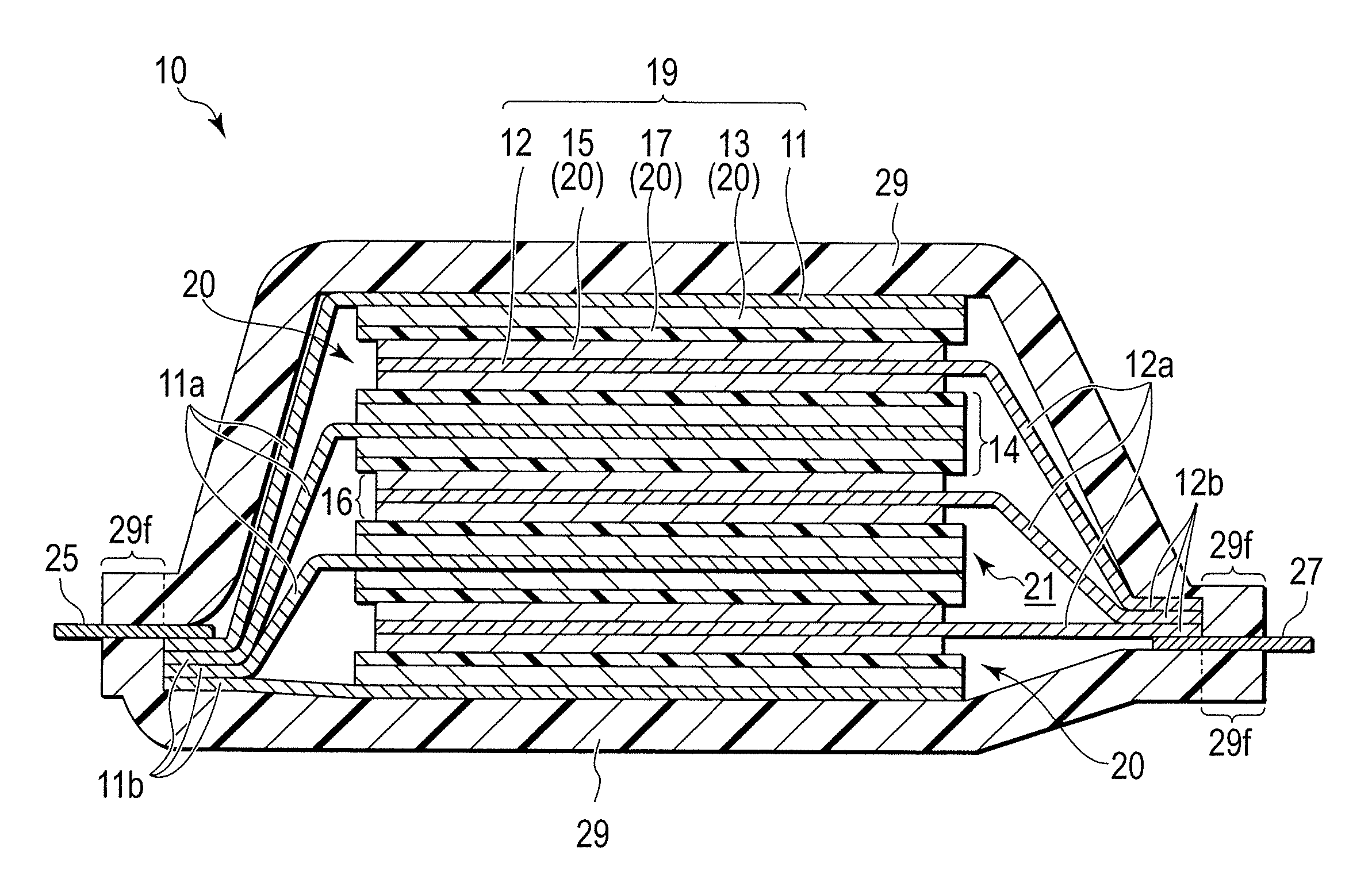
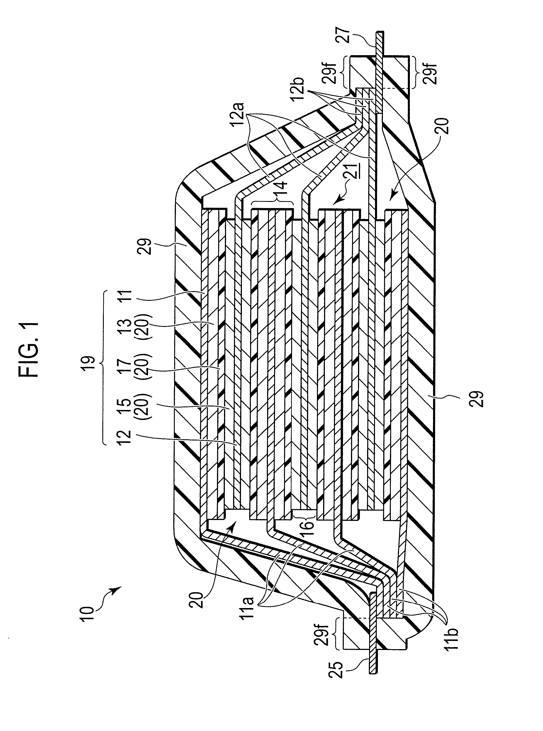
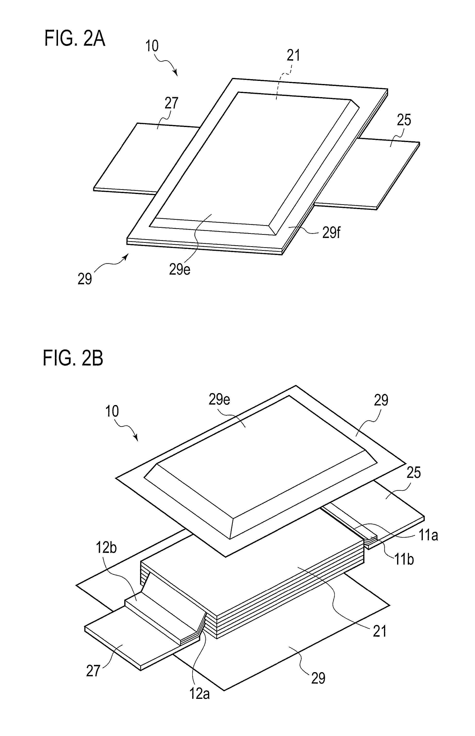
[0031]FIG. 1 is a cross-sectional view schematically showing the structure of a film-wrapped battery 10 of a first embodiment. FIG. 2 shows perspective views schematically showing the film-wrapped battery of the first embodiment. FIG. 2A is a perspective view of the film-wrapped battery in a completed state, and FIG. 2B is an exploded perspective view schematically showing the film-wrapped battery of the first embodiment in FIG. 2A in a state of being broken down to constituent elements.

[0032]

[0033]First, the structure of the film-wrapped battery 10 (an example of a film-wrapped electric...


PUM

PropertyMeasurementUnit
electric currentaaaaaaaaaa
pressureaaaaaaaaaa
pressureaaaaaaaaaa

Abstract

Provided is a method for manufacturing a film-wrapped electrical device, including: a first injection step of depressurizing, to a given pressure lower than atmospheric pressure, the inside of an injection chamber (2) in which a bag-shaped laminate film wrapping member (29) is placed, the laminate film wrapping member (29) having an opening portion (29a) and housing an electrode assembly (21′) including a positive electrode and a negative electrode stacked with a separator therebetween, and injecting part of a predetermined injection amount of an electrolyte solution (20) into the wrapping member (29) through the opening portion (29a); and a second injection step of, after the first injection step, pressurizing the inside of the injection chamber (2) to a pressure higher than the given pressure and injecting the rest of the predetermined injection amount of the electrolyte solution (20).

Description

TECHNICAL FIELD[0001]The present invention relates to a method and a device for manufacturing a film-wrapped electrical device in which an electrical device element such typically as a battery or a capacitor is housed inside a laminate film.BACKGROUND ART[0002]Electrical devices such typically as electrolytic capacitors and batteries are each manufactured by injecting electrolyte solution into a case of a metal or the like with an electrode assembly housed therein to obtain an electrical device element, and then by closing the case. Note that in the explanation in this description, an “electrode assembly” is referred to as one including positive electrodes and negative electrodes stacked with separators therebetween and being in a state (stage) before a series of electrolyte solution injection steps are completed, while an “electrical device element” is referred to as one being in a state (stage) after the series of electrolyte solution injection steps are completed, so as to distin...

Claims


Application Information

Patent Timeline
Patent Type & Authority Applications(United States)
IPC IPC(8): H01M6/04H01G13/04H01M50/119H01M50/121H01M50/124H01M50/178H01M50/548H01M50/553H01M50/618H01M50/636
CPCH01G13/04H01M6/04H01G9/0029H01G9/08H01G11/78H01G11/84H01M50/124H01M50/636H01M50/553H01M50/178H01M50/548H01M50/119H01M50/121H01M50/618Y10T29/49115Y10T29/53278Y02E60/13
Inventor TAKADA, KOICHIMOTOHASHI, YUTA
Owner AUTOMOTIVE ENERGY SUPPLY
Why Eureka
Try Eureka