Heat dissipation device

a heat dissipation device and heat dissipation technology, which is applied in the direction of air heaters, fluid heaters, light and heating apparatus, etc., can solve the problems of poor ventilation, inability to easily dissipate heat, and heat absorbed by buildings, so as to reduce the temperature inside the building, facilitate installation, and simplify manufacturing and assembly of the heat dissipation device

Inactive Publication Date: 2014-12-25
TREASURE UNICORN
View PDF7 Cites 1 Cited by
  • Summary
  • Abstract
  • Description
  • Claims
  • Application Information

AI Technical Summary

Benefits of technology

[0004]A major objective of the present invention is to provide a heat dissipation device for installing on the exterior wall of a building. The heat dissipation device is capable of conducting the heat energy or blocking out the heat energy from sun. The heat dissipation device contains a cuboid body, a number of support elements. The cuboid body is hollow with openings on a top side and a bottom side, respectively. The support elements are positioned in the space inside the cuboid body, thereby partitioning the space into a number of heat dissipation channels. The heat dissipation channels independently connect the top and bottom openings of the cuboid body. A number of the heat dissipation devices can be installed on the outer surface of a building's exterior wall. Through the heat convection provided by the heat dissipation devices, the heat energy produced by sun is dissipated and the building's exterior wall is cooled down. The temperature inside the building is therefore prevented from rising too high.
[0010]Firstly, the heat dissipation device can be directly and conveniently installed on a building's exterior wall. Through heat conduction and convection, the exterior wall is cooled down and the temperature inside the building is reduced.
[0012]Thirdly, the heat dissipation device is able to protect a building's exterior wall from rain. Some old building's rain leakage problem can be resolved as well.
[0013]The function and effect of the present invention are described as follow. By having guiding ditches on the airflow guiding member and having the airflow guiding member detachably configured on the body, the manufacturing and assembly of the heat dissipation device is simplified. The higher cost due to the difficulty in working out guiding holes on extruded heat dissipation devices is as such avoided. Additionally, as the width of the guiding ditch is gradually reduced from the receiving section, through the regulating section, and to the guiding section, the airflow uniformly flows out of the body with an increased speed to form a planar air wall to confine pollutants in the air.

Problems solved by technology

These tall buildings are crowded together and as such lead to poor ventilation.
The heat absorbed by the buildings therefore is trapped and cannot be dissipated easily.

Method used


Image

  • Heat dissipation device
  • Heat dissipation device
  • Heat dissipation device

Examples


Embodiment Construction

[0022]The following descriptions are exemplary embodiments only, and are not intended to limit the scope, applicability or configuration of the invention in any way. Rather, the following description provides a convenient illustration for implementing exemplary embodiments of the invention. Various changes to the described embodiments may be made in the function and arrangement of the elements described without departing from the scope of the invention as set forth in the appended claims.

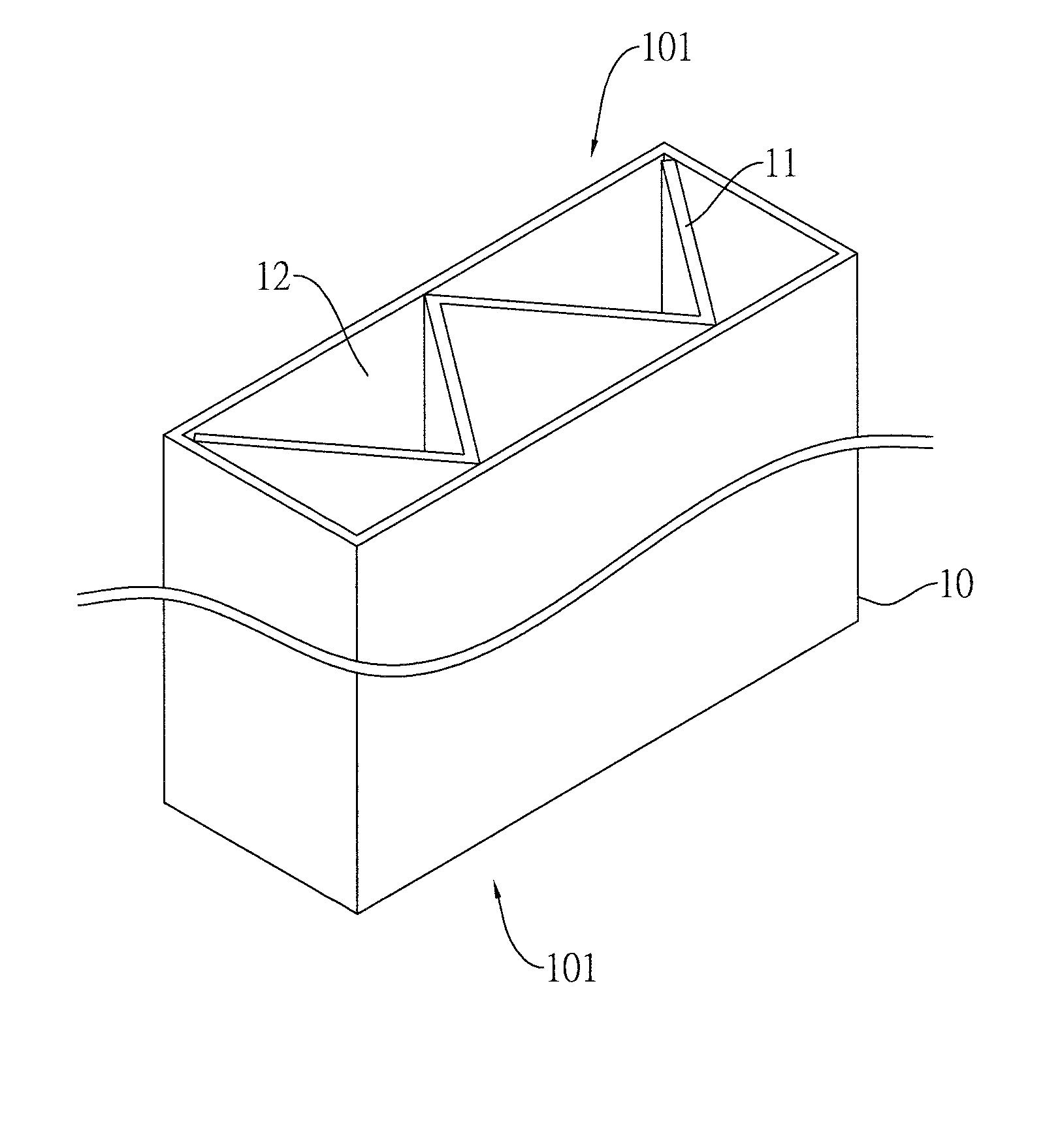
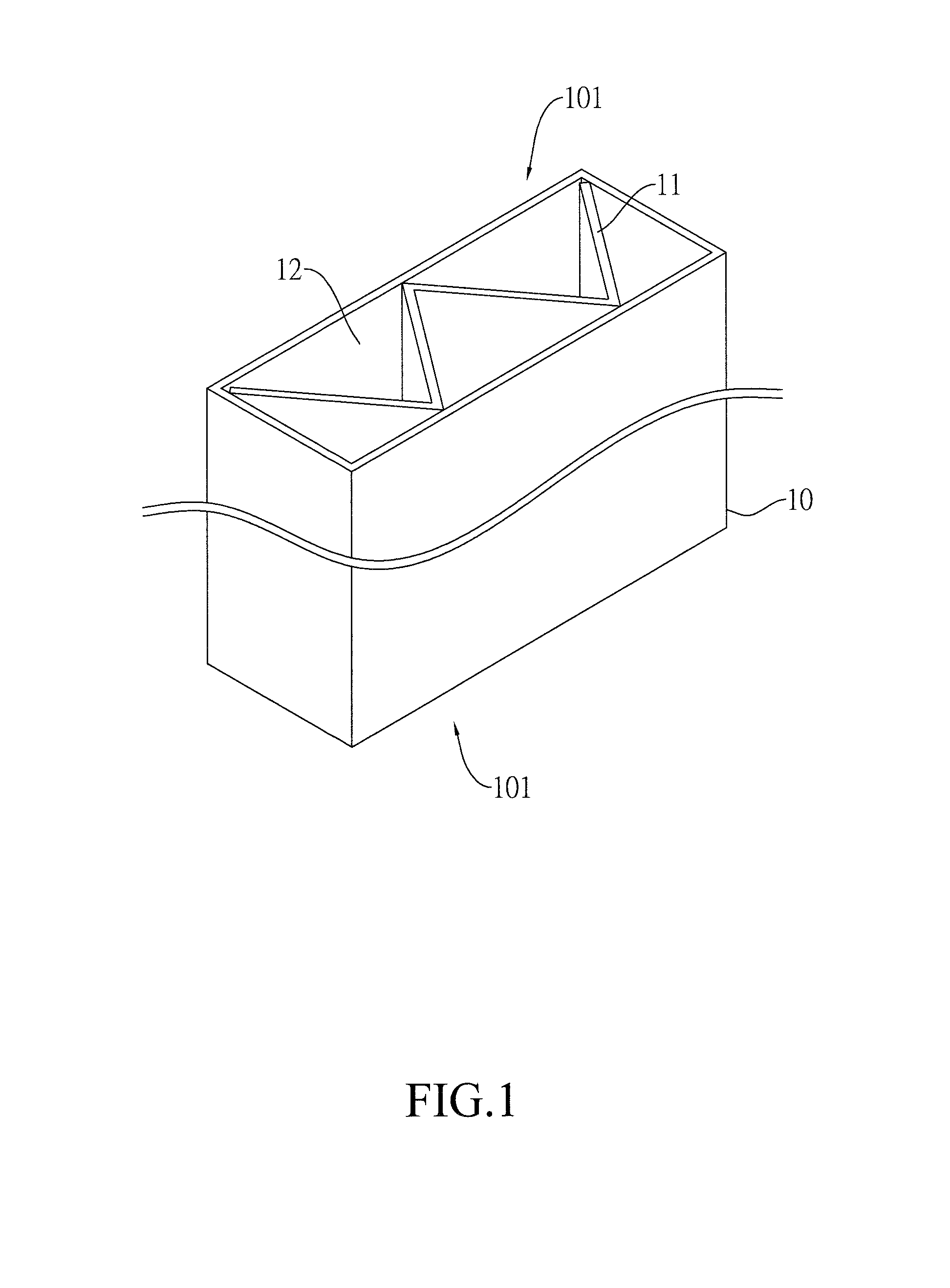
[0023]As illustrated in FIGS. 1 and 2, a heat dissipation device 1 according to a first embodiment of the present invention contains a cuboid body 10, a number of support elements 11, and a number of heat dissipation channels 12. The cuboid body 10 is hollow with openings 101 on a top side and a bottom side, respectively. The support elements 11 are positioned in the space inside the cuboid body 10, thereby partitioning the space into the heat dissipation channels 12. In other words, the heat dissip...


PUM


Abstract

The heat dissipation device is installed on a building's exterior wall for blocking and dissipating the heat energy from sun. The heat dissipation device contains a cuboid body, a number of support elements. The cuboid body is hollow with openings on a top side and a bottom side, respectively. The support elements are positioned in the space inside the cuboid body, thereby partitioning the space into a number of heat dissipation channels. The heat dissipation channels independently connect the top and bottom openings of the cuboid body. A number of the heat dissipation devices can be installed on the outer surface of a building's exterior wall. Through the heat convection provided by the heat dissipation devices, the heat energy produced by sun is dissipated and the building's exterior wall is cooled down. The heat dissipation device can also prevent rain from permeating into the building.

Description

TECHNICAL FIELD OF THE INVENTION[0001]The present invention is generally related to heat dissipation devices, and more particular to a heat dissipation device installed on a building's exterior wall.DESCRIPTION OF THE PRIOR ART[0002]High rise buildings are common for accommodating the ever increasing urban population in the limited city space. These tall buildings are crowded together and as such lead to poor ventilation. The heat absorbed by the buildings therefore is trapped and cannot be dissipated easily.[0003]To overcome this problem, the present inventor provides a reasonably designed and effective solution as outlined in the following.SUMMARY OF THE INVENTION[0004]A major objective of the present invention is to provide a heat dissipation device for installing on the exterior wall of a building. The heat dissipation device is capable of conducting the heat energy or blocking out the heat energy from sun. The heat dissipation device contains a cuboid body, a number of support ...

Claims


Application Information

Patent Timeline
Patent Type & Authority Applications(United States)
IPC IPC(8): F28F1/00
CPCF28F1/00E04F13/007F24S20/66Y02B10/20
Inventor LEE, WEI-CHINGLEE, TZU-ILEE, YU-JIEHLEE, YU-HSUANLEE, PENG-CHIEHLEE, PO-CHANG
Owner TREASURE UNICORN
Why Eureka
Try Eureka