Supercharge Your Innovation With Domain-Expert AI Agents!

Signal adjusting device comprising termination resistor unit in which a signal line is subjected to termination

Active Publication Date: 2014-12-25
FANUC LTD
View PDF1 Cites 2 Cited by
  • Summary
  • Abstract
  • Description
  • Claims
  • Application Information

AI Technical Summary

Benefits of technology

The patent describes a signal adjusting device for a motor control device that can adjust detection signals from different position detectors without needing to change any resistors. The device includes a detection signal receiving unit and a termination resistor with a resistance value that can be adjusted based on the type of position detector. The device can automatically change the resistance value of the termination resistor based on the received detection signal or a changed value can be set and the resistance value changed accordingly. This makes it simple to adjust the detection signals from different position detectors without needing to manually change any resistors.

Problems solved by technology

Accordingly, it is difficult to set an optimum resistance value of a termination resistor unit with respect to a position detector connected to a receiving unit.

Method used


Image

  • Signal adjusting device comprising termination resistor unit in which a signal line is subjected to termination
  • Signal adjusting device comprising termination resistor unit in which a signal line is subjected to termination
  • Signal adjusting device comprising termination resistor unit in which a signal line is subjected to termination

Examples


first embodiment

[0024]An embodiment of a signal adjusting device of the invention will be described with reference to the Drawings. In the Drawings, like components have like numerals.

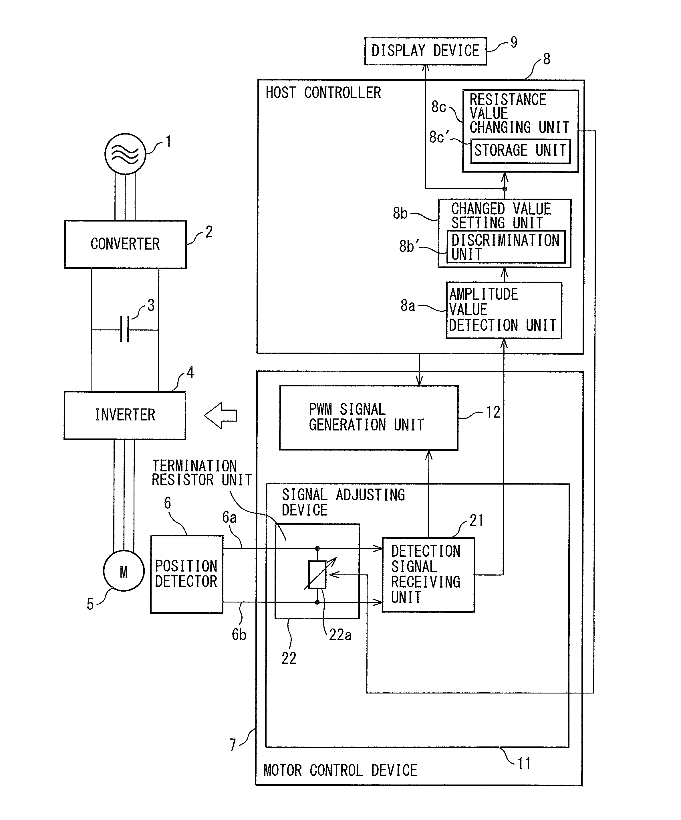
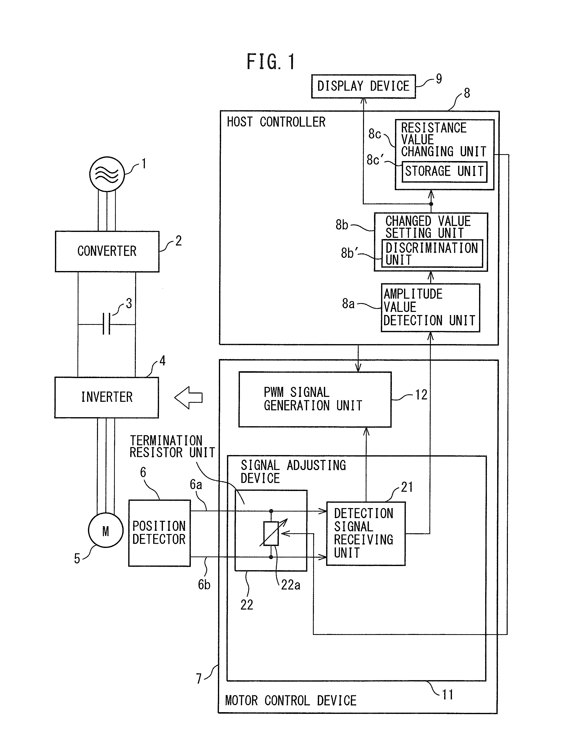
[0025]FIG. 1 is a block diagram of a system comprising a signal adjusting device according to a first embodiment of the invention. The system illustrated in FIG. 1 comprises a three-phase alternating-current power supply 1, a converter 2, a smoothing capacitor 3, an inverter 4, a servo motor 5, a position detector 6, a motor control device 7, a host controller 8, and a display device 9.

[0026]The three-phase alternating-current power supply 1 comprises a commercial alternating-current power supply. The converter 2 comprises, for example, a plurality of (six in the case of three-phase alternating-current) rectifier diodes and transistors each connected antiparallel to the rectifier diodes, and converts alternating-current power supplied from the three-phase alternating-current power supply 1 into direct-current power. T...

second embodiment

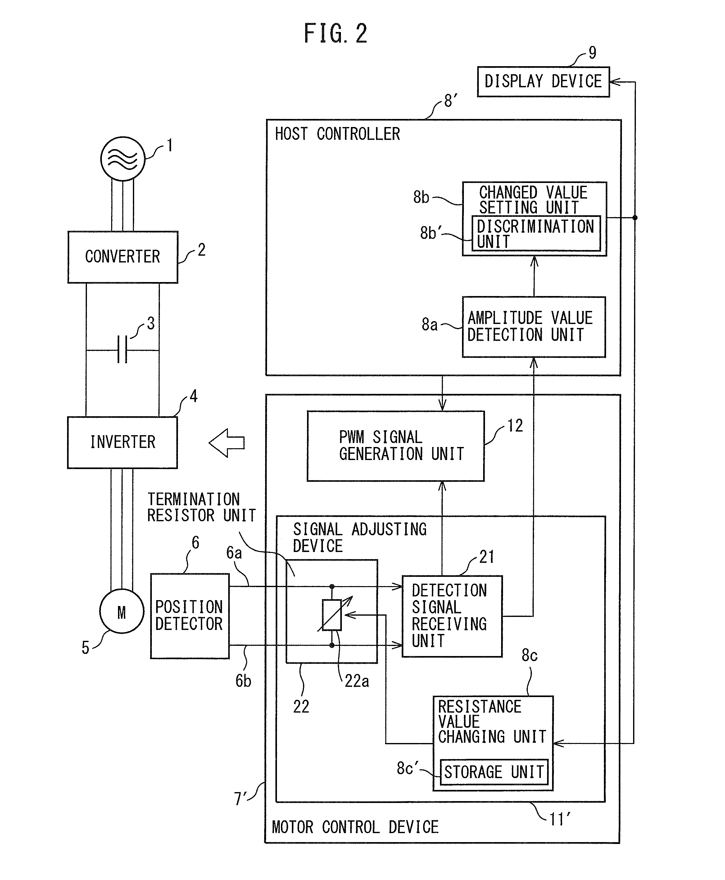
[0047]FIG. 2 is a block diagram of a system comprising a signal adjusting device according to a second embodiment of the invention. In FIG. 2, a signal adjusting device 11′ included in a motor control device 7′ comprises the detection signal receiving unit 21 and termination resistor unit 22 and further comprises the resistance value changing unit 8c; a host controller 8′ comprises the amplitude value detection unit 8a and changed value setting unit 8b, but does not comprise the resistance value changing unit 8c. As illustrated in FIG. 2, the resistance value changing unit 8c may be provided in the signal adjusting device 11′ instead of in the host controller 8′.

third embodiment

[0048]FIG. 3 is a block diagram of a system comprising a signal adjusting device according to a third embodiment of the invention. In FIG. 3, a signal adjusting device 11″ included in motor control device 7″ comprises the detection signal receiving unit 21 and termination resistor unit 22 and further comprises the amplitude value detection unit 8a, changed value setting unit 8b and resistance value changing unit 8c; a host controller 8″ does not comprise the amplitude value detection unit 8a, changed value setting unit 8b and resistance value changing unit 8c. As illustrated in FIG. 3, the amplitude value detection unit 8a, changed value setting unit 8b and resistance value changing unit 8c may be provided in the signal adjusting device 11″ instead of in the host controller 8″. In the present embodiment, the changed value setting unit 8b judges the operation state (operation condition) of the motor 5 in accordance with the command value of the angle of the motor 5 input from the hos...


PUM


Abstract

A detection signal receiving unit receives, via signal lines, a detection signal output from a position detector which is used in a motor control device. The resistance value of a termination resistor unit is changed to a resistance value determined depending on the type of the position detector in accordance with the received detection signal and the reference value determined depending on the type of the position detector.

Description

CROSS-REFERENCE TO RELATED APPLICATIONS[0001]This application is a new U.S. patent application that claims benefit of JP 2013-132876, filed on Jun. 25, 2013, the entire content of JP 2013-132876 is hereby incorporated by reference.FIELD OF THE INVENTION[0002]The present invention relates to a signal adjusting device for adjusting a detection signal which is output from a position detector to be used for a motor control device.BACKGROUND OF THE INVENTION[0003]A signal adjusting device for adjusting a signal when the signal is transmitted from a transmitting unit to a receiving unit via a signal line is known. In the signal adjusting device, a termination resistor unit in which a signal line is subjected to termination processing is connected to the signal line in order that an adverse effect such as variation of the amplitude of a signal, generation of a stepped signal waveform, distortion, turbulence, or the like of a signal due to reflection, or the like of the signal is not impose...

Claims


Application Information

Patent Timeline
IPC IPC(8): H01C10/00H02P29/00
CPCH01C10/00H04L25/0278H04L25/4902
Inventor TSUCHIDA, KUNIO
Owner FANUC LTD
Features
  • R&D
  • Intellectual Property
  • Life Sciences
  • Materials
  • Tech Scout
  • Unparalleled Data Quality
  • Higher Quality Content
  • 60% Fewer Hallucinations
Learn More