
Apparatus and Methods for Perforating Leather Using Perforation Tiles

a technology of perforation dies and perforations, which is applied in the direction of leather clicking/perforating/clicking, leather/skin/hides/pelt mechanical treatment, textiles and paper, etc., can solve the problems of lower plate warping or stretching, difficult and costly manufacture of conventional perforation dies, and high cost of manufacturing

Inactive Publication Date: 2015-01-01
ONTARIO DIE INT
View PDF3 Cites 14 Cited by
  • Summary
  • Abstract
  • Description
  • Claims
  • Application Information

AI Technical Summary

Benefits of technology

The patent describes an apparatus for perforating a sheet of material using a tile holder and a plurality of perforation tiles. The perforation tiles can be mounted on the tile holder and include a fastener plate, a punch plate, and a punch. The punch can be a punch needle or a cutting blade. The apparatus can also include a backing plate to support the punch. The perforation tiles can be arranged in a pattern to create a perforation pattern. The technical effect of this invention is an efficient and precise method for perforating sheets of material.

Problems solved by technology

These conventional perforation dies can be difficult and costly to manufacture.
For example, it can be costly and time consuming to secure each punch to the lower plate.
Furthermore, the lower plate may warp or stretch as each punch is installed.
The accumulation of these distortions can cause alignment issues with other parts of the perforation die such as clearance plates that are positioned underneath the lower plate so as to eject cut material from the punches.
The difficulty and cost may become even greater for complex or detailed perforation patterns that include a large number of punches secured to the lower plate.
Accordingly, the cost of perforation dies can represent a significant expense.
Maintaining these perforation dies can also be costly.
However, the cost of these back-up perforation dies can substantially increase costs, which is generally undesirable.

Method used


Image

  • Apparatus and Methods for Perforating Leather Using Perforation Tiles
  • Apparatus and Methods for Perforating Leather Using Perforation Tiles
  • Apparatus and Methods for Perforating Leather Using Perforation Tiles

Examples


Embodiment Construction

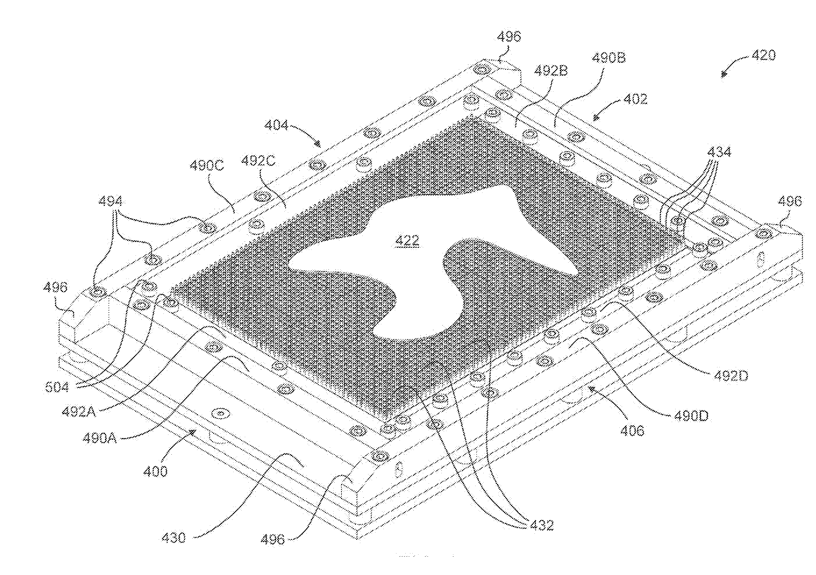
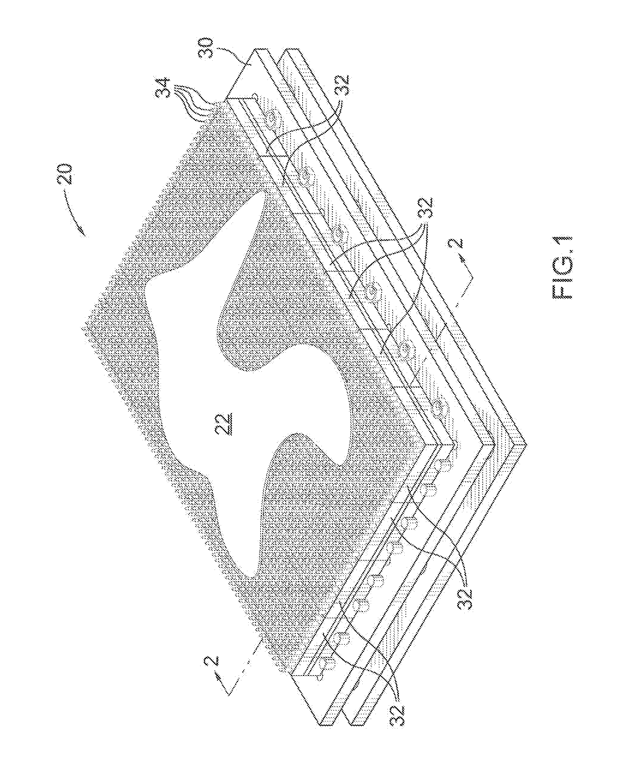
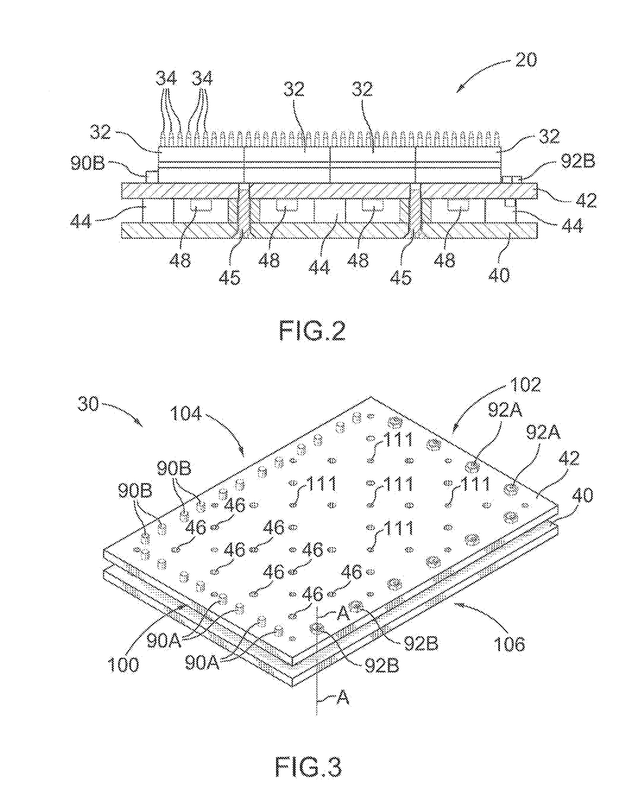
[0007]According to some embodiments, there is provided an apparatus for perforating a sheet of material. The apparatus comprises a tile holder and a plurality of perforation tiles removably mountable to the tile holder. Each perforation tile includes a fastener plate for removably mounting the perforation tile to the tile holder; a punch plate supported by the fastener plate opposite the tile holder, the punch plate having at least one aperture therein; and at least one punch received in the at least one aperture and extending outwardly beyond the punch plate away from the fastener plate for perforating the sheet of material.

[0008]In some embodiments, each perforation tile may further include a backing plate positioned between the fastener plate and the punch plate for supporting the at least one punch.

[0009]In some embodiments, the tile holder may include a plurality of mounting apertures for removably mounting the plurality of perforation tiles to the tile holder. Furthermore, the...


PUM


Abstract

According to some aspects disclosed herein, there is an apparatus for perforating a sheet of material. The apparatus includes a tile holder and a plurality of perforation tiles removably mountable to the tile holder. Each perforation tile includes a fastener plate for removably mounting the perforation tile to the tile holder; a punch plate supported by the fastener plate opposite the tile holder, the punch plate having at least one aperture therein; and at least one punch received in the at least one aperture and extending outwardly beyond the punch plate away from the fastener plate for perforating the sheet of material.

Description

RELATED APPLICATIONS[0001]This application claims the benefit of U.S. provisional application No. 61 / 579,885 filed Dec. 23, 2012, the entire contents of which are hereby incorporated by reference herein for all purposes.TECHNICAL FIELD[0002]The embodiments herein relate to apparatus and methods for perforating sheets of material, and in particular to apparatus and methods of perforating sheets of leather using perforation dies.INTRODUCTION[0003]Perforation dies are often used to perforate sheets of material, for example leather. Conventional perforation dies typically include a lower die shoe (or lower plate) having an array of upwardly extending punches that define a perforation pattern. In use, a sheet of material is placed on the punches of the lower plate and the sheet is pressed downward onto the punches, for example, using a roller press so as to perforate the sheet of material. A cutting pad is often placed between the sheet of material and the roller press.[0004]These conven...

Claims


Application Information

Patent Timeline
IPC IPC(8): C14B5/02B26F1/02C14B5/00B26F1/14
CPCB26F1/14C14B5/02C14B5/00B26F1/02Y10T83/0481D06H7/00Y10T83/944Y10T83/943Y10T83/2213
Inventor PIRO, PETRSCOTT, WESLEY ELTON
Owner ONTARIO DIE INT
Learn More