Device for Distributing Gases in Liquids

a technology for distributing gases and liquids, applied in the direction of fuel gas production, mixing methods, transportation and packaging, etc., can solve the problems of weak points of adhesive bonded or welded seams, cracks may form in proximity to welded seams, and the aerating mat will be unable to withstand the high internal pressure in the area of welded joints or seams, etc., to achieve uniform bubble distribution, reliable sealing, and high rigidity.

Active Publication Date: 2015-01-01
NORRES SCHLAUCHTECHNIK GMBH
View PDF2 Cites 10 Cited by
  • Summary
  • Abstract
  • Description
  • Claims
  • Application Information

AI Technical Summary

Benefits of technology

[0024]With regard to this embodiment, it is further suggested that the gas inlet of the device be integrated into the end fitting. The gas connection can be integrated into the end fitting by inserting a core into the casting or injection mold, which is shaped like the gas connection, and is again removed from the end fitting after the plastic has cured. In addition to the gas connection, a threaded connector for a hose can also be integrated into the end fitting. As an alternative, the hose or line used to supply gas to the device can be encapsulated via casting or injection molding, and thereby integrated into the end fitting. The advantage to integrating the gas connection or other components into the end fitting is that it produces an especially reliable seal, even at high pressures.
[0025]Another embodiment of the invention provides that the lower side of the aerating element is airtight, and in particular comprises no holes, perforations or the like. The advantage to this is that all of the air can exit the device via the perforated upper side of the aerating element, making it possible to achieve a particularly uniform bubble distribution. In addition, an airtight lower side prevents large air bubbles from forming on the lower side of the device, and their buoyancy from pressing the latter toward the water surface. Finally, a non-perforated area has a higher stiffness than a perforated area, so that expansion on the lower side is lower than on the upper side. The advantage to this is that the upper side arches more strongly when exposed to an internal pressure than the lower side, making it possible to achieve an even better distribution of air bubbles on the upper side.
[0026]According to another instruction of the invention, it is proposed that the upper side of the aerating element comprises perforated areas interrupted by airtight strips that run in the longitudinal and / or transverse direction of the aerating element. This also has the effect of the upper side arching outwardly more strongly in the less stiff perforated areas than in the area of the stiffer, airtight strips. In turn, the advantage here involves an improved distribution of air bubbles.
[0027]Finally, a further embodiment of the invention suggests that a rail be provided for accommodating and stiffening the device. The rail makes it possible to increase the stiffness of the device. In particular in very long devices or devices with pliable support elements, this has the advantage of preventing uncontrolled deformation given a high internal pressure or strong flow of water. The rail can be permanently secured to the bottom of a water basin, so that the aerating element with the support element can be clamped into the rail if needed. As an alternative, the rail can also be assembled and disassembled together with the aerating element and support element.

Problems solved by technology

The disadvantage to aerating mats known from WO 2007 / 051150 A2 is that the adhesively bonded or welded seams represent weak points.
Since the upper film must expand to open the holes, the danger becomes that the aerating mat will be unable to withstand the high internal pressure in the area of the welded joints or seams.
In particular, cracks may form in proximity to the welded seams, since the films strongly expand in this region, while almost no expansion can take place in the area of the welded seam itself.
As a consequence, the film tears in the area of the welded joints or seams, and the aerating mat fails.
Another disadvantage lies in the fact that such aerating mats are complicated and expensive to manufacture, for example since ultrasound or high-frequency welding devices must be used for welding together the upper film and lower film.
Known tube aerators have the disadvantage of a bubble distribution unsuitable for aerating larger surfaces.
However, one disadvantage to circular cross sections is that the air exits the hose in a radial direction, causing a portion of the air to also exit toward the bottom and side.
As a result, circular cross sections cannot be used to uniformly distribute the bubbles over a flat surface, for example over the bottom of a water basin.
Another disadvantage to tube aerators with cylindrical support tubes lies in the fact that the support tube exhibits a cavity.
The air present in the cavity generates buoyancy, thereby hampering the assembly of tube aerators underwater.
However, this leads to another disadvantage, since the filling makes it more complicated and expensive to manufacture and transport the tube aerators.
Finally, another disadvantage of tube aerators involves the intricate piping.
In addition, tube aerators often have very high buoyant forces (with the cavity not filled) or very high downforces (e.g., when filled with concrete).
In combination with the unilateral clamping, both lead to very high torque loads, so that very stable, and hence very expensive, piping must be installed.

Method used


Image

  • Device for Distributing Gases in Liquids
  • Device for Distributing Gases in Liquids
  • Device for Distributing Gases in Liquids

Examples


Embodiment Construction

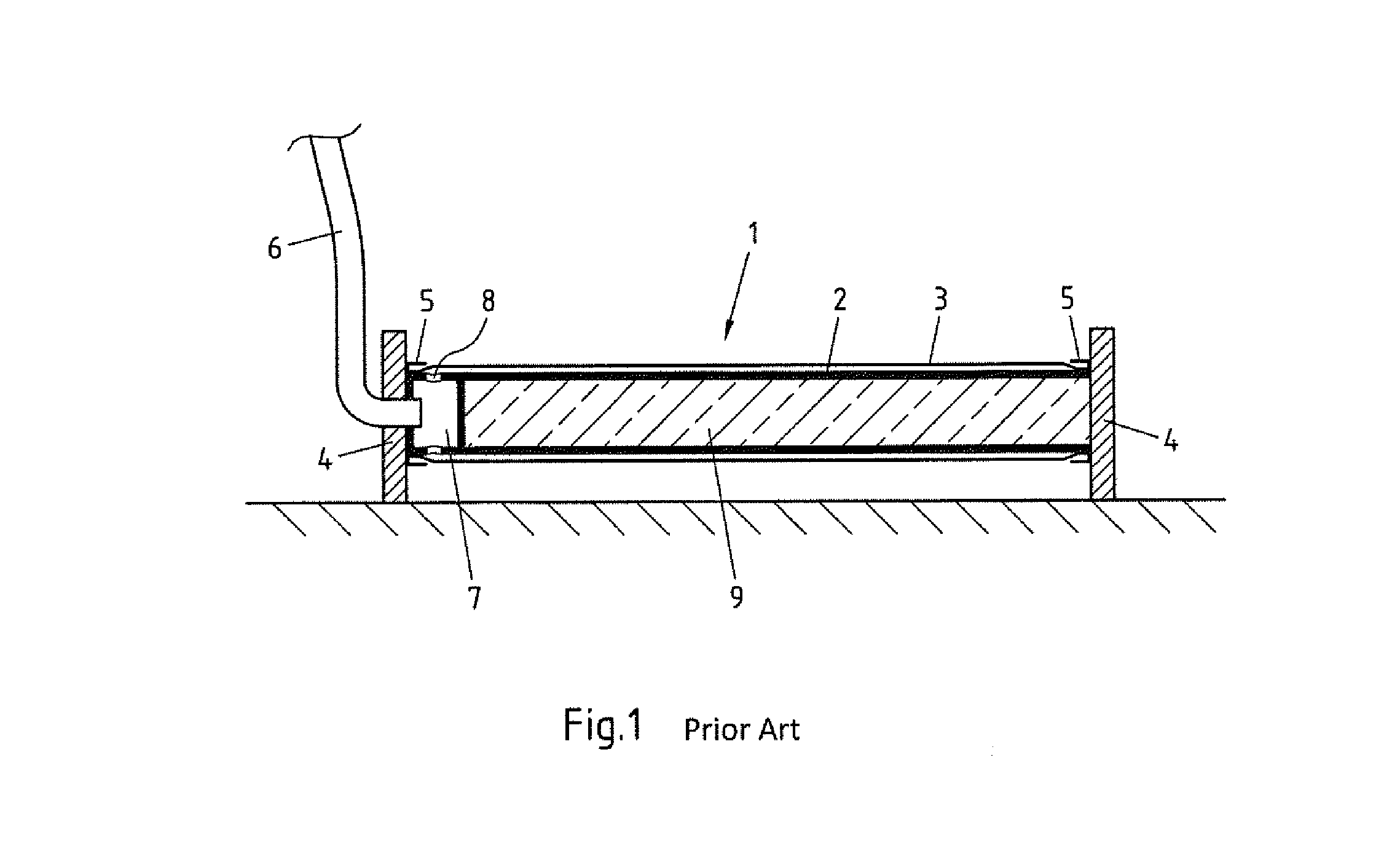
[0036]FIG. 1 shows a tube aerator known from prior art. The tube aerator 1 depicted on FIG. 1 largely corresponds to the tube aerator shown on FIG. 3 of DE 20 2006 004 514 U1. The tube aerator 1 encompasses a cylindrical tube 2 over which a perforated hose 3 is slipped. Both ends of the tube aerator 1 are provided with disks 4 having receptacles 5 that accommodate the hose 3 and seal it away from the tube 2. Air can stream into a distribution chamber 7 through a line 6, and from there be distributed via radial boreholes 8 into the gap between the tube 2 and perforated hose 3. Given a high enough internal pressure, the air can exit the tube aerator 1 through the holes provided in the hose 3. Finally, the tube aerator 1 exhibits a cavity 9 filled with concrete.

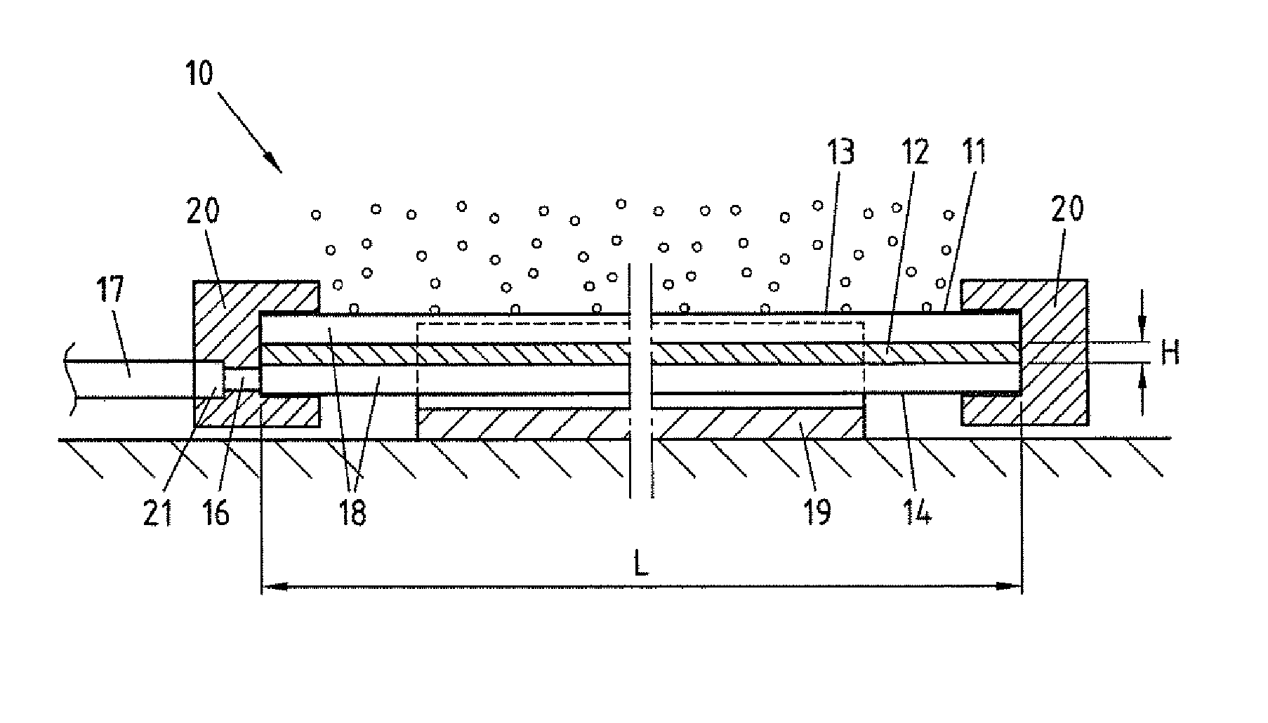
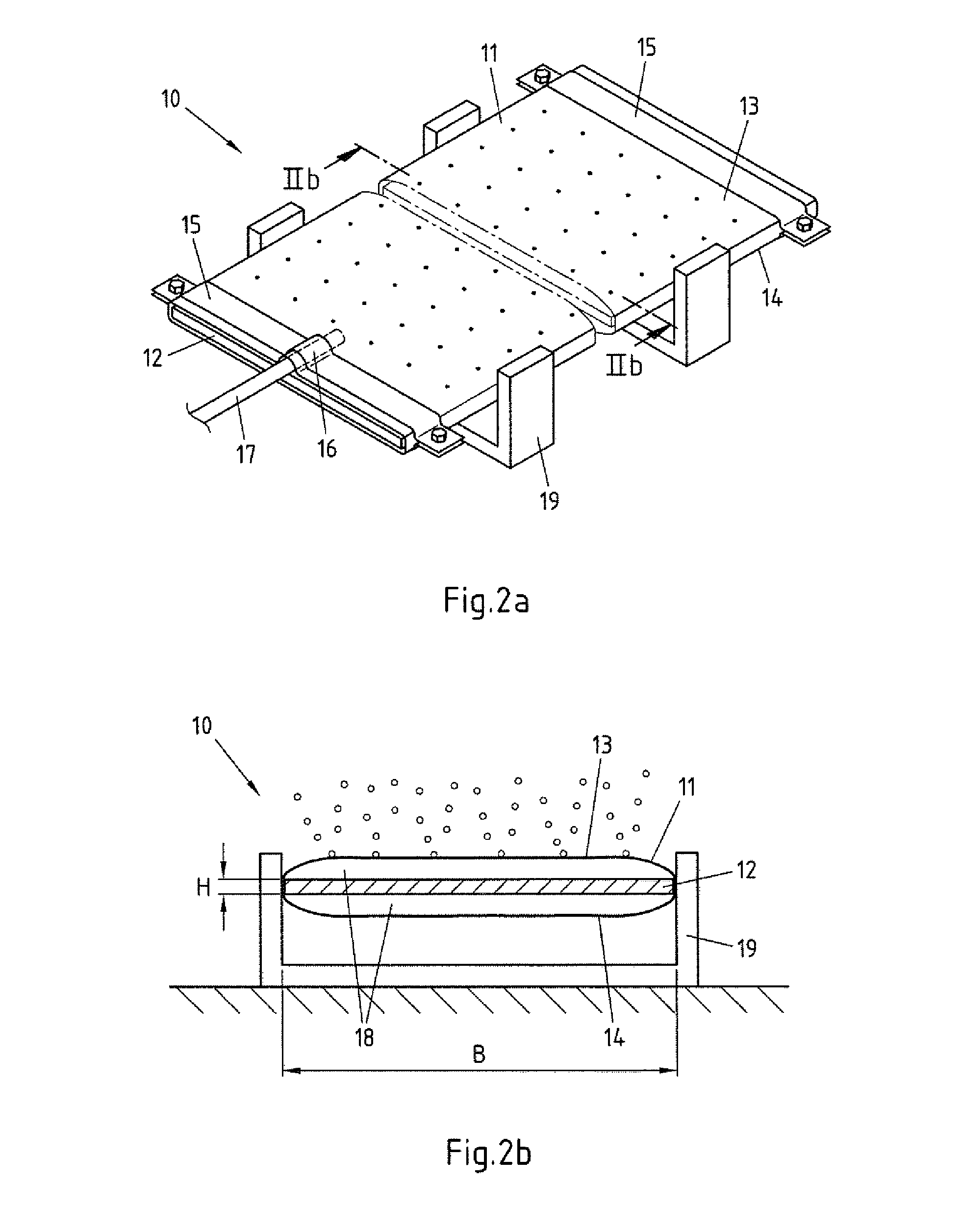
[0037]FIG. 2a shows a perspective view depicting a first embodiment of a device 10 according to the invention for distributing gases in liquids. The device 10 comprises an aerating element 11, which in the device 10 exemplarily ...


PUM

PropertyMeasurementUnit
heightaaaaaaaaaa
widthaaaaaaaaaa
widthaaaaaaaaaa

Abstract

A device for distributing gases in liquids, comprising: an aerating element made out of plastic, with an upper side and a lower side joined with the upper side, a support element, and a gas inlet, wherein the aerating element comprises at least one cavity that can be filled with gas through the gas inlet, wherein at least the area of the upper side of the aerating element comprises holes, perforations or the like as the gas outlet, and wherein the support element is situated in the cavity of the aerating element. In order to enable a uniform and reliable aeration of larger water surfaces in a cost-effective manner, it is proposed that the width of the support element be greater than its height.

Description

CROSS-REFERENCE TO RELATED APPLICATION[0001]This application claims priority to German Patent Application No. 10 2013 106 845.6 filed Jul. 1, 2013, the disclosure of which is hereby incorporated in its entirety by reference.BACKGROUND OF THE INVENTION[0002]1. Field of the Invention[0003]The invention relates to a device for distributing gases in liquids, comprising: an aerating element made of plastic, with an upper side and a lower side joined with the upper side, a support element, and a gas inlet, wherein the aerating element comprises at least one cavity that can be filled with gas through the gas inlet, wherein at least the area of the upper side of the aerating element comprises holes, perforations or the like as the gas outlet, and wherein the support element is situated in the cavity of the aerating element.[0004]2. Description of Related Art[0005]The progression of many biological or chemical processes is also determined among other factors by the gas content of the liquids...

Claims


Application Information

Patent Timeline
Patent Type & Authority Applications(United States)
IPC IPC(8): C02F1/74B01F3/04
CPCC02F1/74B01F2215/0052B01F3/04099B01F3/04269B01F2003/04312B01F23/231264B01F23/23124B01F23/231B01F23/2311
Inventor MOLLEN, BURKHARD
Owner NORRES SCHLAUCHTECHNIK GMBH
Why Eureka
Try Eureka