Wireless power transmission device
a power transmission device and wireless technology, applied in the direction of transformer/inductance details, transformer/inductance circuit, inductance, etc., can solve the problem of not providing sufficient power transmission efficiency, and achieve the effect of improving power transmission efficiency, q factor, and improving power feeding uni
- Summary
- Abstract
- Description
- Claims
- Application Information
AI Technical Summary
Benefits of technology
Problems solved by technology
Method used
Image
Examples
first embodiment
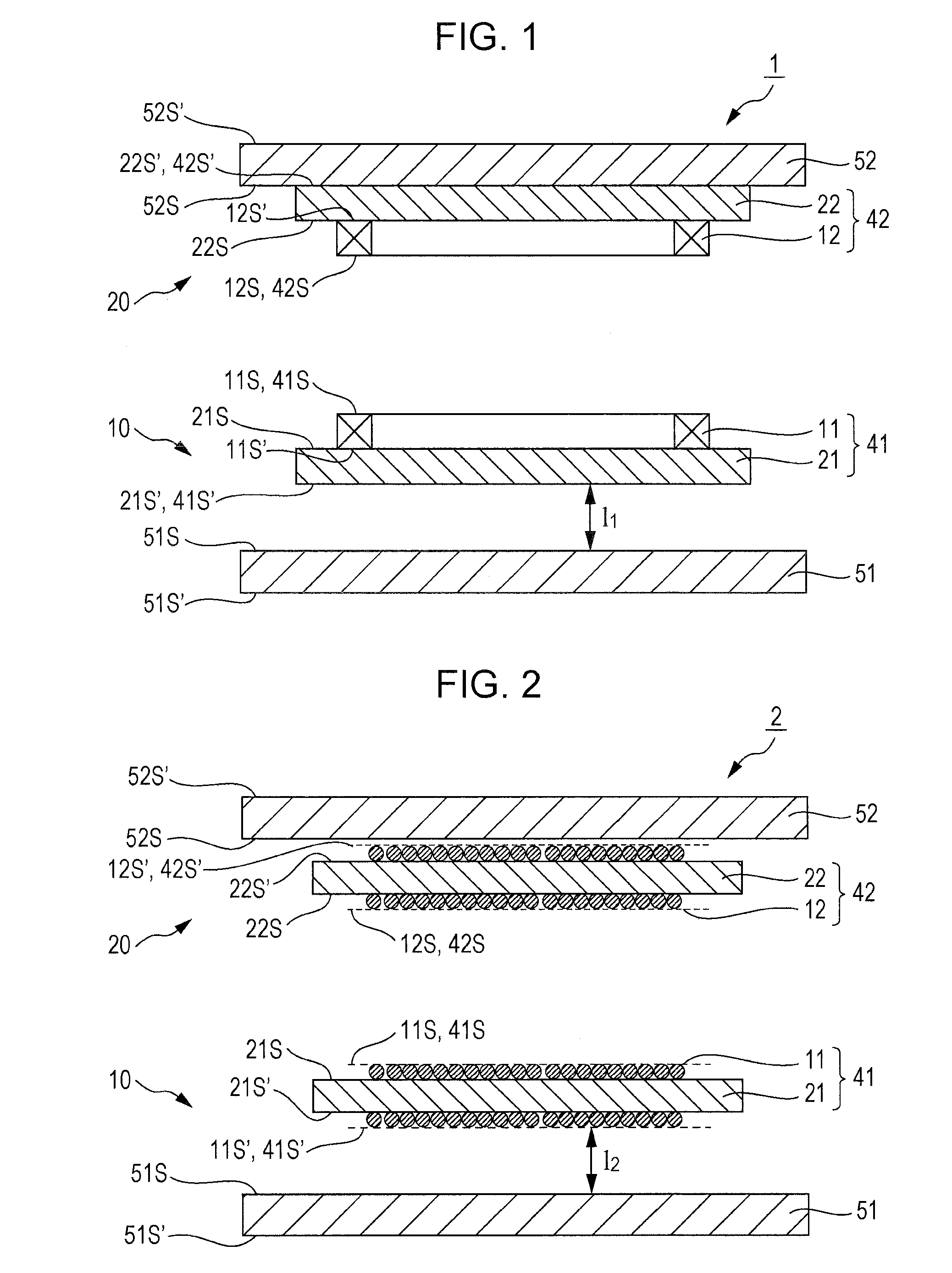
[0019]FIG. 1 is a cross-sectional view of a wireless power transmission device according to a first embodiment of the present invention.
[0020]A wireless power transmission device 1 according to the first embodiment includes a power feeding unit 10 and a power receiving unit 20 described below.
(Power Feeding Unit 10)
[0021]The power feeding unit 10 includes a feeding-side coil 41, and a feeding-side shield member 51. The feeding-side coil 41 has a primary winding 11, and a primary magnetic core 21 having two principal surfaces 215 and 21S′ that face each other. The feeding-side shield member 51 has two principal surfaces 515 and 51S′ that face each other. The principal surface 21S′ representing one of the principal surfaces of the primary magnetic core 21, and the principal surface 51S representing one of the principal surfaces of the feeding-side shield member 51 are disposed so as to face each other.
[0022]The primary winding 11 is a wire that is wound in a planar shape, and provided...
second embodiment
[0036]FIG. 2 is a cross-sectional view of a wireless power transmission device according to a second embodiment of the present invention.
[0037]A wireless power transmission device 2 according to the second embodiment includes a power feeding unit 10 and a power receiving unit 20 described below.
(Power Feeding Unit 10)
[0038]The power feeding unit 10 includes a feeding-side coil 41, and a feeding-side shield member 51. The feeding-side coil 41 has a primary winding 11, and a primary magnetic core 21 having two principal surfaces 21S and 21S′ that face each other. The feeding-side shield member 51 has two principal surfaces 51S and 51S that face each other. The principal surface 21S′ representing one of the principal surfaces of the primary magnetic core 21, and the principal surface 51S representing one of the principal surfaces of the feeding-side shield member 51 are disposed so as to face each other.
[0039]The primary winding 11 is a wire that is wound around the primary magnetic co...
example
[0055]Hereinafter, the present invention will be described in more detail by way of an example. However, the present invention is not limited to the example described below.
[0056]A power feeding unit was prepared by using a feeding-side coil and a feeding-side shield member described below. Further, a power receiving unit was prepared by using a receiving-side coil and a receiving-side shield member described below.
(Power Feeding Unit)
[0057]Feeding-side coil: a planar winding (primary winding) having a length of 35 cm, a width of 35 cm, and a thickness of 5 mm was bonded to one principal surface of a ferrite plate (primary magnetic core) having a length of 40 cm, a width of 40 cm, and a thickness of 2 mm.
[0058]Feeding-side shield member: an aluminum plate having a length of 40 cm, a width of 40 cm, and a thickness of 2 mm was used.
(Power Receiving Unit)
[0059]Receiving-side coil: a planar winding (secondary winding) having a length of 20 cm, a width of 20 cm, and a thickness of 5 mm ...
PUM
 Abstract
Description
Claims
Application Information
 - R&D
- Intellectual Property
- Life Sciences
- Materials
- Tech Scout
- Unparalleled Data Quality
- Higher Quality Content
- 60% Fewer Hallucinations
Browse by: Latest US Patents, China's latest patents, Technical Efficacy Thesaurus, Application Domain, Technology Topic, Popular Technical Reports.
© 2025 PatSnap. All rights reserved.Legal|Privacy policy|Modern Slavery Act Transparency Statement|Sitemap|About US| Contact US: help@patsnap.com


