Supercharge Your Innovation With Domain-Expert AI Agents!

Electro-magnetic contactor

Inactive Publication Date: 2015-01-01
LSIS CO LTD
View PDF15 Cites 5 Cited by
  • Summary
  • Abstract
  • Description
  • Claims
  • Application Information

AI Technical Summary

Benefits of technology

The present invention is an electromagnetic contactor that solves problems of contamination and vibration. It includes a fixed contact with a protection base to prevent foreign substances from entering and reduce vibration. The protection base prevents contamination during fabrication and also reduces the amount of external foreign substances from flowing in during use. Additionally, the protection base reduces vibration and stabilizes the fixed contact, reducing the likelihood of conduction failure.

Problems solved by technology

When foreign substances adhere to a contact surface between the fixed contact 3 and the movable contact 9, an electromagnetic force is weakened and it occurs a phenomenon in which the fixed contact 3 and the movable contact 9 cannot be properly brought into contact with each other, thereby increasing a conduction failure rate due to this.
Furthermore, the fixed contact 3 may be turned over during a component transport process or the like even in the fabrication process, thereby causing foreign substances to be adhered to the contact surface.
However, even in the above invention, it may be impossible to prevent dust from flowing in through the opening portion of a grid, and difficult to cope with the adhesion of foreign substances generated during the fabrication process or the like.

Method used


Image

  • Electro-magnetic contactor
  • Electro-magnetic contactor
  • Electro-magnetic contactor

Examples


Embodiment Construction

[0032]Hereinafter, a preferred embodiment of the present invention will be described in detail with reference to the accompanying drawings to such an extent that the present invention can be easily implemented by a person having ordinary skill in the art to which the present invention pertains, but it does not mean that the technical concept and scope of the present invention are limited due to this.

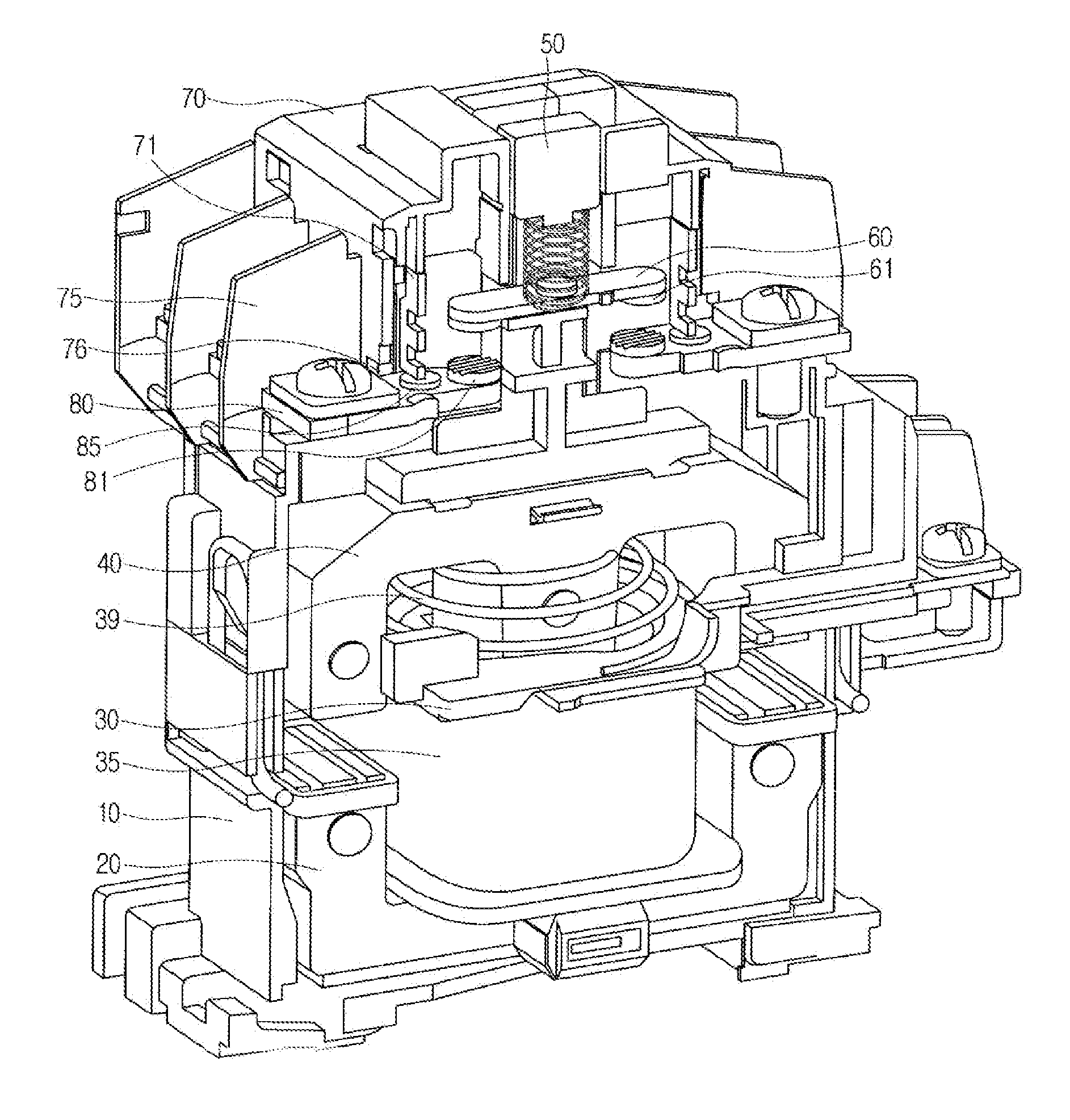
[0033]FIG. 4 is an internal perspective view illustrating an electromagnetic contactor according to the present disclosure, and FIG. 5 is a perspective view illustrating a fixed contact of the electromagnetic contactor according to the present disclosure, and FIGS. 6a and 6b are a plan view and a front view of FIG. 5, and FIG. 7 is a partial perspective view illustrating an electromagnetic contactor according to the present disclosure. An embodiment of the present disclosure will be described in detail with reference to the drawings.

[0034]An electromagnetic contactor according to an embo...


PUM


Abstract

An electromagnetic contactor according to an embodiment of the present disclosure may include a lower frame; a fixed core provided to be inserted into the lower frame; a bobbin provided at an upper portion of the fixed core; a coil coupled to the bobbin; a movable core provided at an upper portion of the bobbin; a cross bar coupled to an upper portion of the movable core; a movable contact coupled to the cross bar to move in an upward and downward direction; an upper frame configured to cover the lower frame; and a fixed contact fixed to part of the upper frame, wherein a protection base is formed to be protruded from an intermediate portion of the fixed contact.

Description

CROSS-REFERENCE TO RELATED APPLICATIONS[0001]Pursuant to 35 U.S.C. §119(a), this application claims the benefit of earlier filing date and right of priority to Korean Patent Application No. 10-2013-0076579, filed on Jul. 1, 2013, the contents of which are all hereby incorporated by reference herein in its entirety.BACKGROUND OF THE INVENTION[0002]1. Field of the Invention[0003]The present invention relates to an electromagnetic contactor, and more particularly, an electromagnetic contactor provided with a fixed contact formed with a protection base stably fixed to prevent the inflow of foreign substances and reduce vibration, thereby reducing the contamination of a fixed contact point as well as reducing a conduction failure rate.[0004]2. Description of the Related Art[0005]In general, electromagnetic contactor is a type of electrical circuit switching device for transferring a mechanical drive and current signal using the principle of an electromagnet, and provided in various indus...

Claims


Application Information

Patent Timeline
IPC IPC(8): H01H1/64
CPCH01H1/64H01H1/06H01H50/023H01H50/305H01H50/546
Inventor RHO, DONG, CHAE
Owner LSIS CO LTD
Features
  • R&D
  • Intellectual Property
  • Life Sciences
  • Materials
  • Tech Scout
  • Unparalleled Data Quality
  • Higher Quality Content
  • 60% Fewer Hallucinations
Learn More