Imager module for a camera, camera and method for manufacturing the imager module

Active Publication Date: 2015-01-01
ROBERT BOSCH GMBH
View PDF5 Cites 4 Cited by
  • Summary
  • Abstract
  • Description
  • Claims
  • Application Information

AI Technical Summary

Benefits of technology

The patent text describes a clamping device that has three contact points. These contact points are clearly defined by the three points and are not overdefined. This ensures that each clamping plane has a defined contact at each of the three contact points. The device also has flat tips that help avoid particles. Overall, this design improves the performance of the clamping device.

Problems solved by technology

The disadvantage of such systems is that, in the case of the press fit joint, particles may be abraded from the press ribs, which may then fall into the rear lens space in a disruptive manner and end up on the image sensor, whereby the image quality may be considerably impaired.
In particular, focusing by sliding the objective back and forth in the objective holder results in great particle abrasion.
Moreover, depending on the tolerance situation, the press fit in part introduces great forces into the objective and the tube area of the objective holder.
However, the disadvantage of such systems is that the two joining partners generally have complex surfaces; however, real surfaces generally deviate from the theoretical shape, so that the points of contact are often random, which may cause a negative impact on the precise position of the optical axis and the orientation in three spatial angles, i.e., a tilt of the optical axis of the objective with respect to the axis of the symmetry of the tube area.

Method used


Image

  • Imager module for a camera, camera and method for manufacturing the imager module
  • Imager module for a camera, camera and method for manufacturing the imager module
  • Imager module for a camera, camera and method for manufacturing the imager module

Examples


Embodiment Construction

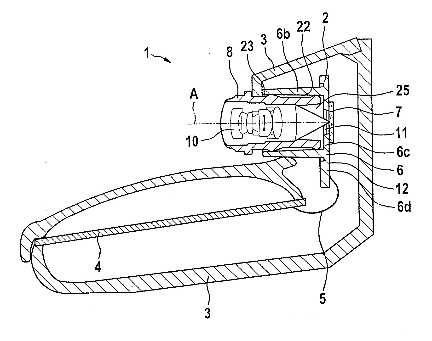
[0044]A camera 1 is provided for attachment in a vehicle, e.g., on the interior side of a windshield of the vehicle, and includes an imager module 2 which is shown in greater detail in the following figures. Camera 1 further includes an, e.g., two-piece camera housing 3 and a circuit carrier board 4, e.g., a printed circuit board 4, including electronic components which are not shown in detail here, such as a control unit and a data interface. Imager module 2 is contacted with circuit carrier board 4 via a connection, e.g., wire bonds 5 or a flexible line.

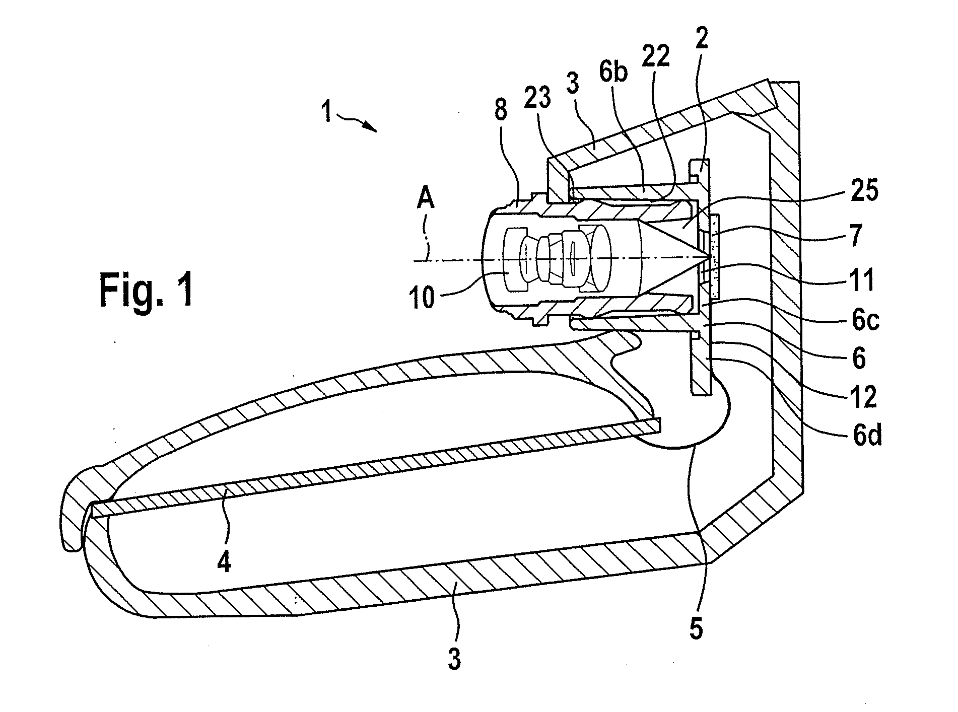
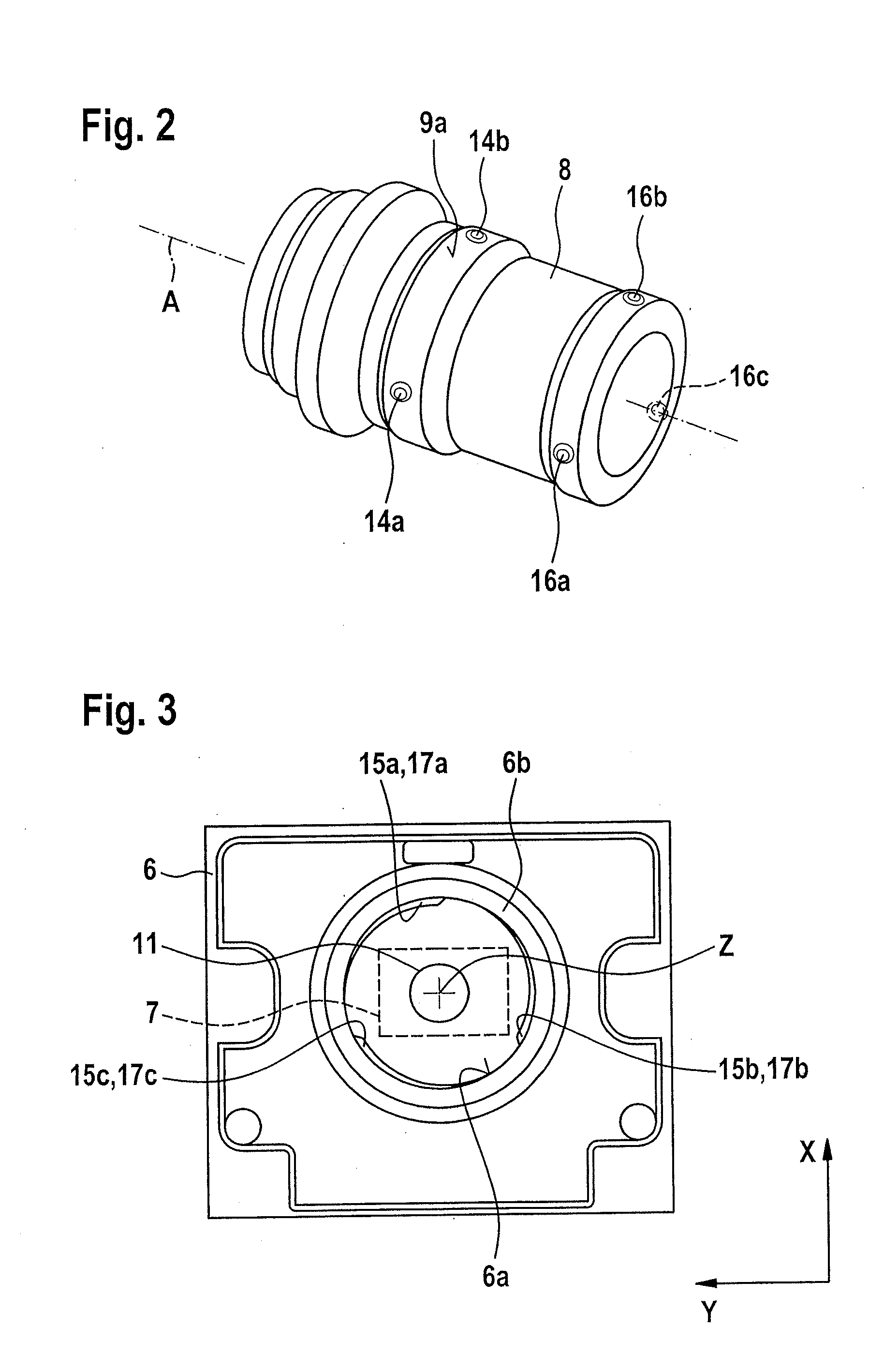
[0045]Imager module 2 forms a self-contained unit, which is subsequently accommodated in camera housing 3, and includes an objective holder 6, an image sensor 7 and an objective 8 accommodated in objective holder 6. Objective 8, in turn, includes a lens mount 9 and multiple lenses 10 accommodated in lens mount 9. Image sensor 7 and objective 8 define an optical axis A.

[0046]Objective holder 6 includes a tube area 6b having a cylind...


PUM

PropertyMeasurementUnit
Radiusaaaaaaaaaa
Areaaaaaaaaaaa
Elevationaaaaaaaaaa

Abstract

An imager module for a camera includes: at least one objective holder; an image sensor mounted on the objective holder; and an objective accommodated in a tube area of the objective holder. Multiple contact areas are formed between an outer surface of the objective and the cylindrical inner surface of the tube area of the objective holder by frictional engagement. For this purpose, a first clamping plane is formed in the tube area, and a second clamping plane is formed which is offset from the first clamping plane along a longitudinal axis of the tube area, multiple first contact areas being formed in the first clamping plane, and multiple second contact areas being formed in the second clamping plane and situated distributed around the longitudinal axis in a circumferential direction.

Description

BACKGROUND OF THE INVENTION[0001]1. Field of the Invention[0002]The present invention relates to an imager module for a camera, to a camera including such an imager module, and to a method for manufacturing the imager module.[0003]2. Description of the Related Art[0004]Such imager modules are used in particular in cameras for vehicles which are attached in the interior area of the vehicle and, for example, detect an exterior area outside the vehicle through a pane or also the interior area of the vehicle. The imager module is accommodated and contacted in a camera housing and may represent a finished, focused unit.[0005]The imager module generally includes an objective holder, which may have a one-piece or also a multi-piece design and generally includes a tube area or a tubular area into which the objective is inserted in the longitudinal direction. The objective holder may have a multi-piece design and include a sensor carrier to which the tubular objective holder is attached; mor...

Claims


Application Information

Patent Timeline
IPC IPC(8): H04N5/225
CPCH04N5/2253H04N5/2257H04N5/2252Y10T29/49004H04N23/51H04N23/54H04N23/57H04N23/55
Inventor STEINBERGER, WERNER
Owner ROBERT BOSCH GMBH
Why Eureka
Try Eureka