
Device for gripping and inserting an insert element

Inactive Publication Date: 2015-09-10
XNOV IP
View PDF3 Cites 2 Cited by
  • Summary
  • Abstract
  • Description
  • Claims
  • Application Information

AI Technical Summary

Benefits of technology

The present invention aims to solve the problems of previous hip joint inserts by proposing an insertion device that can securely and accurately insert the insert into the cup without causing damage or cracks. The device allows for easy and reliable insertion, even at angled positions, reducing the risk of complications during surgery. The device also allows for adjustable power to optimize the blow given to the insert and ensure optimal fit between the insert and cup. Additionally, the device includes a locking mechanism to secure the piston in a loaded position and a trigger for easy and quick release of the piston. This ensures a safe and reliable device for hip joint replacement.

Problems solved by technology

Insertion devices are already known that comprise a rod, an impaction head fixed to the end of the rod and designed to come into contact with the insert and gripping means designed for temporarily holding the insert to the insertion device when the impaction head is in contact with the insert, the latter being then adjusted by force to the cup by means of a shock or impaction applied to the rod by the surgeon to secure it in such a way that it is difficult, almost impossible, to remove.
Said devices of the prior art are complicated to use and do not guarantee a reliable impaction force in the right direction.
It is often the case that either the insert is misaligned in relation to the cup prior to its impaction, or the axis in which the impaction is performed is not set accurately in a direction suitable for joining the insert and the cup perfectly.
As a result the insert could be fitted badly in the cup, which over the long term may lead to breaking and associated complications for the patient (new operation for removing the defective cup, which is often shattered, and refitting a cup).

Method used


Image

  • Device for gripping and inserting an insert element
  • Device for gripping and inserting an insert element
  • Device for gripping and inserting an insert element

Examples


Embodiment Construction

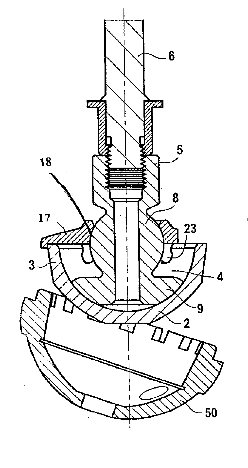
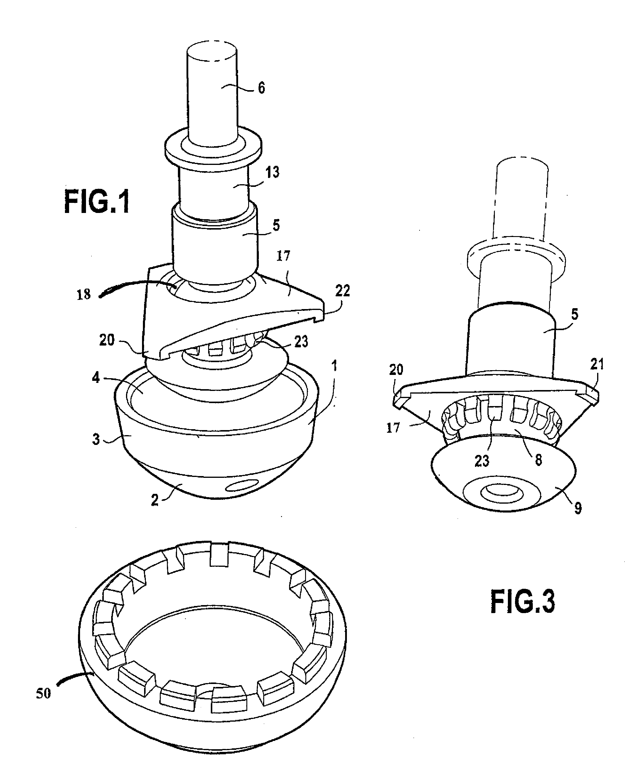
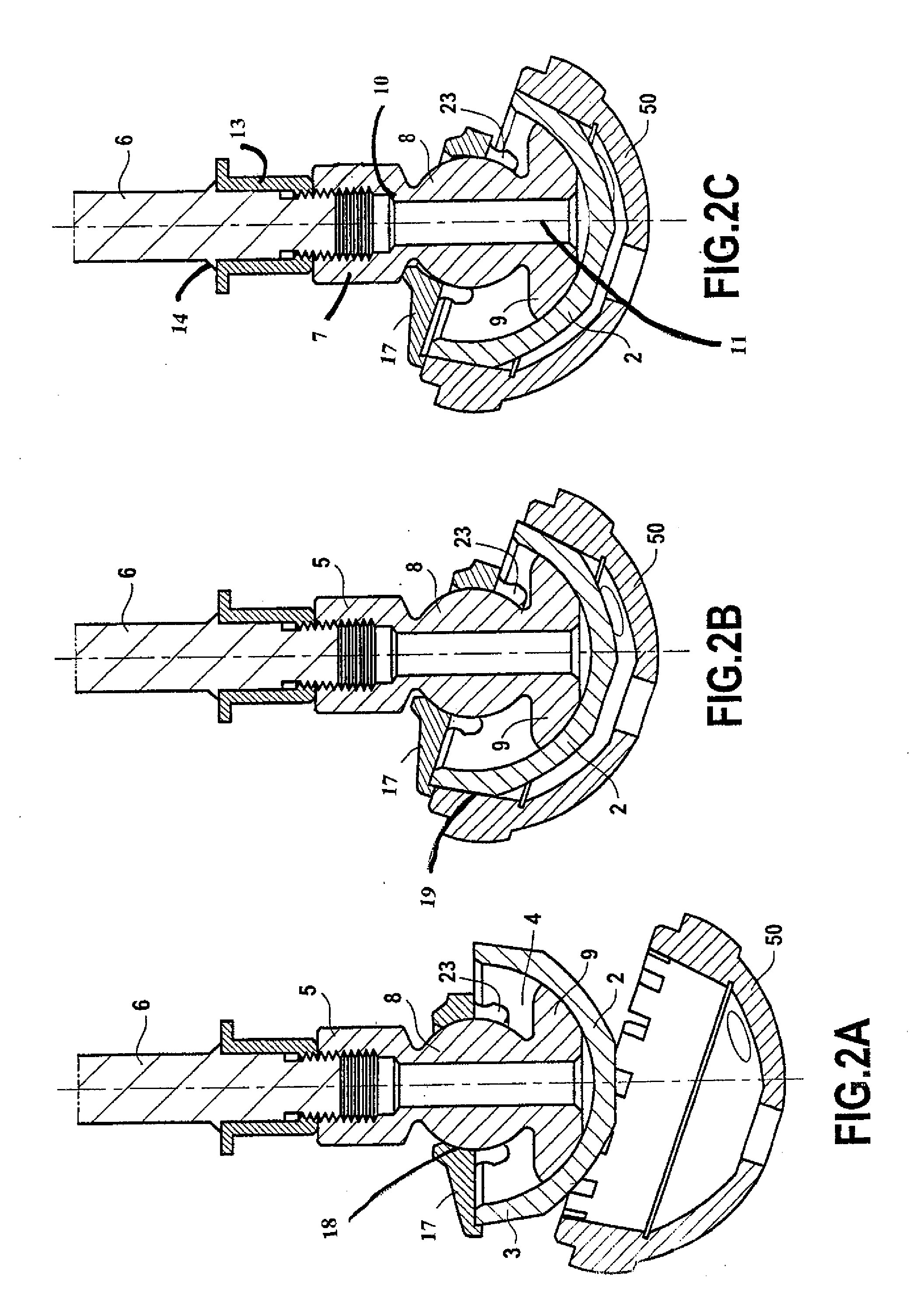
[0034]FIG. 1 is a perspective view of an insertion device according to an embodiment of the invention of an insert 1 made of ceramic material in a cup 50. The insert 1 made of ceramic material is formed by a ceramic body, in particular made of alumina ceramic material, with an exterior surface in the form of a spherical cap 2 terminated by a part 3 of the upper or proximal edge with a slightly truncated cone shape. The insert is hollow and comprises an inner cavity 4 the wall of which has a hemispherical form. In particular, the shaped cone of the truncated cone part 3 of the edge of the outer surface of the insert forms an angle of about 3 to 5° relative to the vertical axis of symmetry of the insert made of ceramic material.

[0035]The insertion device is formed by a circular cylindrical rod 6 to which an impaction end piece 5 has been adapted at its distal end. The end piece 5 comprises a tubular proximal section 7 which is tapped to receive the threaded end of the rod 6 therein, t...


PUM


Abstract

Device for inserting an insert (1), made in particular of ceramic material, by impaction into a cup (50) designed to be received in the cotyl of a hip, comprising: means (17, 20, 21, 22) for gripping the insert, in particular at an upper free edge of the insert; a rod (5, 6) for the application of shock designed to be held by the surgeon and for the application of an impaction shock to the insert when it is held by the gripping means opposite the cup to be introduced therein; and an impaction head (9) with a surface designed to come in contact with at least one insert part, in particular the inner surface of a hollow of the insert.

Description

TECHNICAL FIELD[0001]The present invention relates to a device for inserting an insert element, made in particular of ceramic material, into a cup which is itself designed to be received in the cotyloidal cavity of a hip of a patient.BACKGROUND ART[0002]Insertion devices are already known that comprise a rod, an impaction head fixed to the end of the rod and designed to come into contact with the insert and gripping means designed for temporarily holding the insert to the insertion device when the impaction head is in contact with the insert, the latter being then adjusted by force to the cup by means of a shock or impaction applied to the rod by the surgeon to secure it in such a way that it is difficult, almost impossible, to remove.[0003]Said devices of the prior art are complicated to use and do not guarantee a reliable impaction force in the right direction. It is often the case that either the insert is misaligned in relation to the cup prior to its impaction, or the axis in w...

Claims


Application Information

Patent Timeline
IPC IPC(8): A61F2/46
CPCA61F2/4609A61F2/34A61F2/4637A61F2002/30332A61F2002/30378A61F2002/30538A61F2002/4681
Inventor BIEGUN, JEAN-FRANCOISBIEGUN, FREDERIQUELOEHLE, PASCAL
Owner XNOV IP
Learn More