Cell trapping device

a cell and cell technology, applied in the field of cell trapping devices, can solve problems such as difficulty in monitoring and measuring blood cell components

Inactive Publication Date: 2015-01-01
HITACHI CHEM CO LTD +1
View PDF5 Cites 14 Cited by
  • Summary
  • Abstract
  • Description
  • Claims
  • Application Information

AI Technical Summary

Benefits of technology

[0020]According to the present application, it is possible to provide a cell trapping device that enables observation of cells trapped on a filter without disassembling the device.

Problems solved by technology

In order to efficiently detect CTCs from the blood cell components, it has been necessary to isolate the blood cell components, and, thus, it has been very difficult to observe and measure the blood cell components.

Method used


Image

  • Cell trapping device
  • Cell trapping device
  • Cell trapping device

Examples


Embodiment Construction

[0028]Hereinafter, exemplary embodiments of a cell trapping device of the present application will be explained in detail with reference to the accompanying drawings, but the invention is not limited thereto.

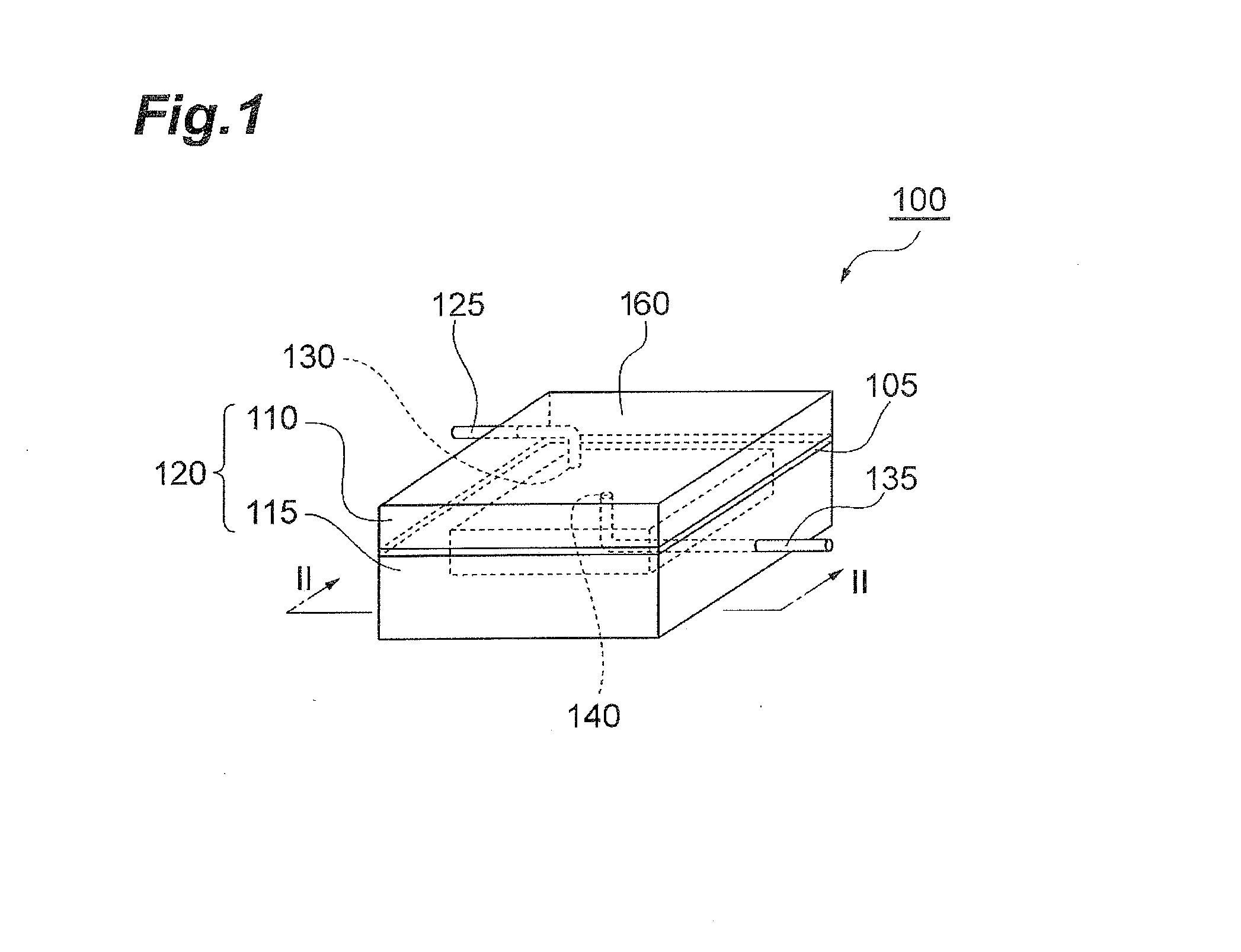
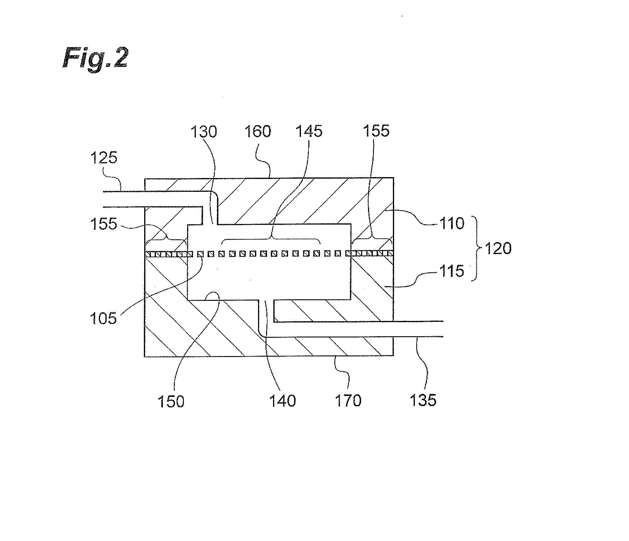
[0029]FIG. 1 is a perspective view illustrating an exemplary embodiment of a cell trapping device. FIG. 2 is a cross-sectional view taken along a line II-II of FIG. 1.

[0030]As shown in FIG. 1 and FIG. 2, a cell trapping device 100 includes a housing 120 that includes an inlet opening 130 connected to an inlet line 125 through which a cell dispersion liquid is introduced and an outlet opening 140 connected to an outlet line 135 through which the cell dispersion liquid is discharged; and a filter 105 which is positioned within the housing 120 and includes a trapping region for trapping cancer cells contained in the cell dispersion liquid. At least a part of the trapping region is formed of an observation region 145 for observing the trapping region from the outside, the inlet line...


PUM

PropertyMeasurementUnit
angleaaaaaaaaaa
angleaaaaaaaaaa
angleaaaaaaaaaa

Abstract

A cell trapping device includes a housing that includes an inlet opening connected to an inlet line through which a cell dispersion liquid is introduced and an outlet opening connected to an outlet line through which the cell dispersion liquid is discharged; and a filter which is positioned within the housing and includes a trapping region for trapping cancer cells contained in the cell dispersion liquid. The filter is bonded to the housing, at least a part of the trapping region is formed of an observation region for observing the trapping region from the outside, the inlet line and the inlet opening are arranged at outer positions than the observation region when viewed from a normal line direction of the filter, and the inlet line is extended along an in-plane direction of the filter.

Description

TECHNICAL FIELD[0001]The present application relates to a cell trapping device that traps cancer cells contained in a cell dispersion liquid.BACKGROUND ART[0002]Cancer ranks high as a cause of death around the world. Particularly, in Japan, the death toll due to cancer reaches 300,000 per year. Thus, there has been a demand for early diagnosis and treatment for that. People have died of cancer mostly due to metastatic relapse of cancer. Metastatic relapse of cancer occurs when cancer cells flow through blood vessels or lymphatic vessels from a primary lesion and adhere to and infiltrate into arterial walls of other organs and form a micrometastatic lesion. Such cancer cells circulating in the body through blood vessels or lymphatic vessels have been referred to as “Circulating Tumor Cells” (hereinafter, sometimes referred to as “CTC”).[0003]Blood contains a lot of blood cell components such as red blood cells or white blood cells, and platelets, and the number thereof has been known...

Claims


Application Information

Patent Timeline
Patent Type & Authority Applications(United States)
IPC IPC(8): G01N1/40
CPCG01N1/4005B01L3/502753B01L2300/0681B01L2300/0874C12M47/02G01N15/0272G01N15/06G01N2001/4088G01N2015/0065C12M47/04
Inventor KIKUHARA, YOSHIHITOKANBARA, HISASHIGESUZUKI, TAKAHIROMATSUNAGA, TADASHIYOSHINO, TOMOKOHOSOKAWA, MASAHITO
Owner HITACHI CHEM CO LTD
Why Eureka
Try Eureka