Electric vehicle traction control system and method

a technology of electric vehicles and control systems, applied in process and machine control, instruments, navigation instruments, etc., can solve problems such as driver inability to drive, slippage, adversely affecting acceleration performance and driving stability,

Active Publication Date: 2015-01-01
BOREALIS TECH LTD
View PDF7 Cites 22 Cited by
  • Summary
  • Abstract
  • Description
  • Claims
  • Application Information

AI Technical Summary

Benefits of technology

[0015]It is yet a further object of the present invention to provide a traction control system and method for an aircraft equipped with drive wheels driven by electric drive motors to move the aircraft autonomously on the ground without reliance on aircraft engines.

Problems solved by technology

When the coefficient of friction of the surface is less than the force exerted, the wheel will slip during acceleration of the vehicle, adversely affecting acceleration performance and driving stability.
Slippage can occur as a result of excessive accelerative forces applied to vehicle wheels or inadequate wheel to surface friction that can be present with wet or icy conditions.
The driver may not be immediately aware that slippage is occurring, however, and may not be able to take corrective action as quickly as required.
Neither of the systems described in the aforementioned patents would effectively control traction in a vehicle that is powered solely by an electric drive motor or other electric drive means

Method used


Image

  • Electric vehicle traction control system and method
  • Electric vehicle traction control system and method
  • Electric vehicle traction control system and method

Examples


Embodiment Construction

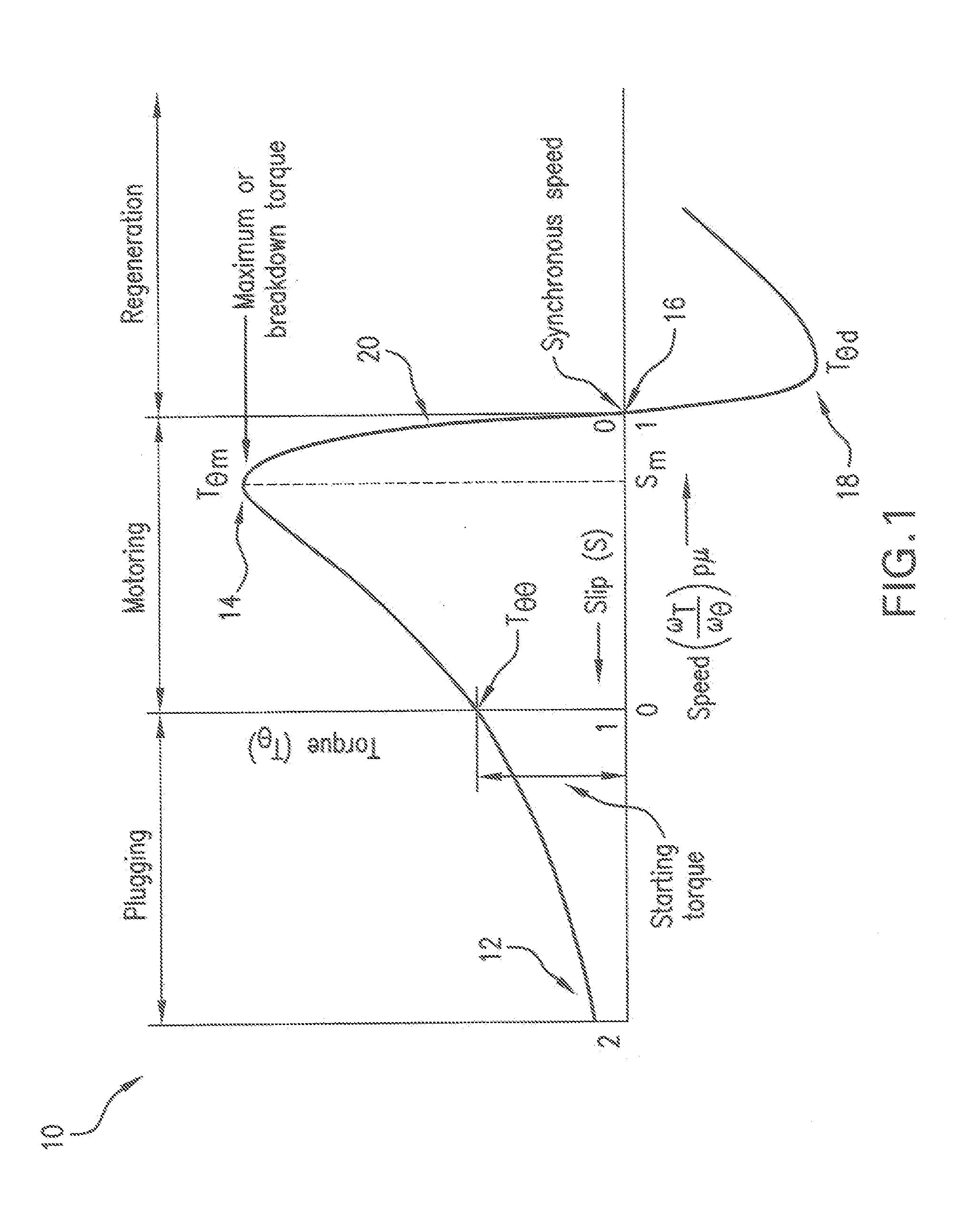
[0023]Traction control in any vehicle, whether powered by an electric motor or another power source, requires modulating the rotational speed of the drive wheels to match the vehicle travel speed over a ground surface. Wheel rotational speed is generally reduced by braking, for example, although other methods can also reduce speed, depending on the vehicle's power source. Driving traction is produced by the force of the vehicle's wheels against the ground surface and the surface coefficient of adhesion or friction, μ. The force of a wheel, which is directed perpendicularly toward the ground surface, may be described as including a proportional force normal to the surface and a proportional force parallel to the surface. The proportional force normal to the surface is part of the traction frictional force. If a sufficiently large torque or drive force is applied from the wheel to the ground surface tangent to a contact point between the wheel and the surface, the frictional grip, or ...


PUM


Abstract

A traction control system and method are provided for electric vehicles with at least one drive wheel powered by an electric drive motor to maintain optimum maximum traction while the vehicle is driven on the ground. The traction control system includes drive means capable of transmitting torque through a vehicle drive wheel and controllable to move the vehicle over a ground surface. A preferred drive means is an electric motor designed to move the vehicle at desired ground speeds in response to operator input. Operator input requests a desired speed, and the system determines drive wheel torque required to produce the desired speed and provides maximum current to produce maximum torque to drive the vehicle with optimum traction at the desired speed. The system uses constant feedback to find maximum current corresponding to torque required for an inputted speed request to automatically control traction in any electric powered vehicle.

Description

PRIORITY CLAIM[0001]This application claims priority from U.S. Provisional Patent Application No. 61 / 568,993, filed 9 Dec. 2011, the disclosure of which is incorporated herein.TECHNICAL FIELD[0002]The present invention relates generally to traction control systems and methods of traction control and specifically to a system and method for traction control in an electric powered vehicle, including an aircraft driven on the ground movement by an electric powered drive wheel.BACKGROUND OF THE INVENTION[0003]Traction control systems help to prevent or limit a vehicle's wheels from slipping during acceleration on different surfaces. Traction of a vehicle is established as its wheels contact a surface so that when the wheels are rotated, usually by a driving force, the vehicle will be moved along the surface in a desired direction. The combination of the coefficient of friction and the force exerted by a wheel against the surface produces traction. When the coefficient of friction of the ...

Claims


Application Information

Patent Timeline
Patent Type & Authority Applications(United States)
IPC IPC(8): B60L15/20B60L50/16
CPCB60L15/20B60L3/108B60L7/006B60L7/18B60L11/14B60L11/1803B60L11/1877B60L15/2009B60L2200/10B60L2220/12B60L2220/14B60L2220/16B60L2220/18B60L2240/12B60L2240/421B60L2240/423B60L2240/425B60L2240/461Y02T10/70B60L50/16B60L50/51B60L50/66Y02T10/64Y02T10/7072Y02T10/72B60L3/106B64C25/405
Inventor COX, ISAIAH, W.
Owner BOREALIS TECH LTD
Why Eureka
Try Eureka