Switch structure

a switch and structure technology, applied in the direction of contacts, electrical equipment, enclosures/screens of contacts, etc., can solve the problems of affecting the operation space of the screw, the limitation of the form of the lead inserted in the cavity, and the structural design and application of the conventional switch, so as to enhance the lead locking ability of the switch structure and increase the structural strength of the switch structure

Active Publication Date: 2015-01-08
SWITCHLAB +1
View PDF1 Cites 23 Cited by
  • Summary
  • Abstract
  • Description
  • Claims
  • Application Information

AI Technical Summary

Benefits of technology

[0011]It is therefore a primary object of the present invention to provide an improved switch structure connectable with both bare lead and flat-head terminal lead. The switch structure includes a main body formed with at least one cavity. A retainer member and a conductive metal member are arranged in the cavity for pressing the terminal lead into electrical connection with the conductive metal member. A reciprocally movable carrier body is assembled with the retainer member. The carrier body has an arm assembled with an elastic member. A restriction body is disposed in the cavity. The restriction body is formed with a chamber for receiving the arm and the elastic member of the carrier body, The restriction body restricts the moving direction or distance of the carrier body to increase the structural strength of the switch structure and enhance the lead locking ability of the switch structure.

Problems solved by technology

The conventional switch has a problem in structural design and application.
Such limitation not only affects the operation space of the screw 35, but also leads to limitation of the form of the lead inserted in the cavity 11 for electrically connecting with the conductive metal member 20.
As known by those who are skilled in this field, this will complicate the structure of the washer 30 and increase the manufacturing cost of the washer 30.
This lowers the structural strength of the washer 30 and deteriorates the ability to lock the terminal lead.
This causes limitation of the operation space of the screw 35.

Method used


Image

  • Switch structure
  • Switch structure
  • Switch structure

Examples


Embodiment Construction

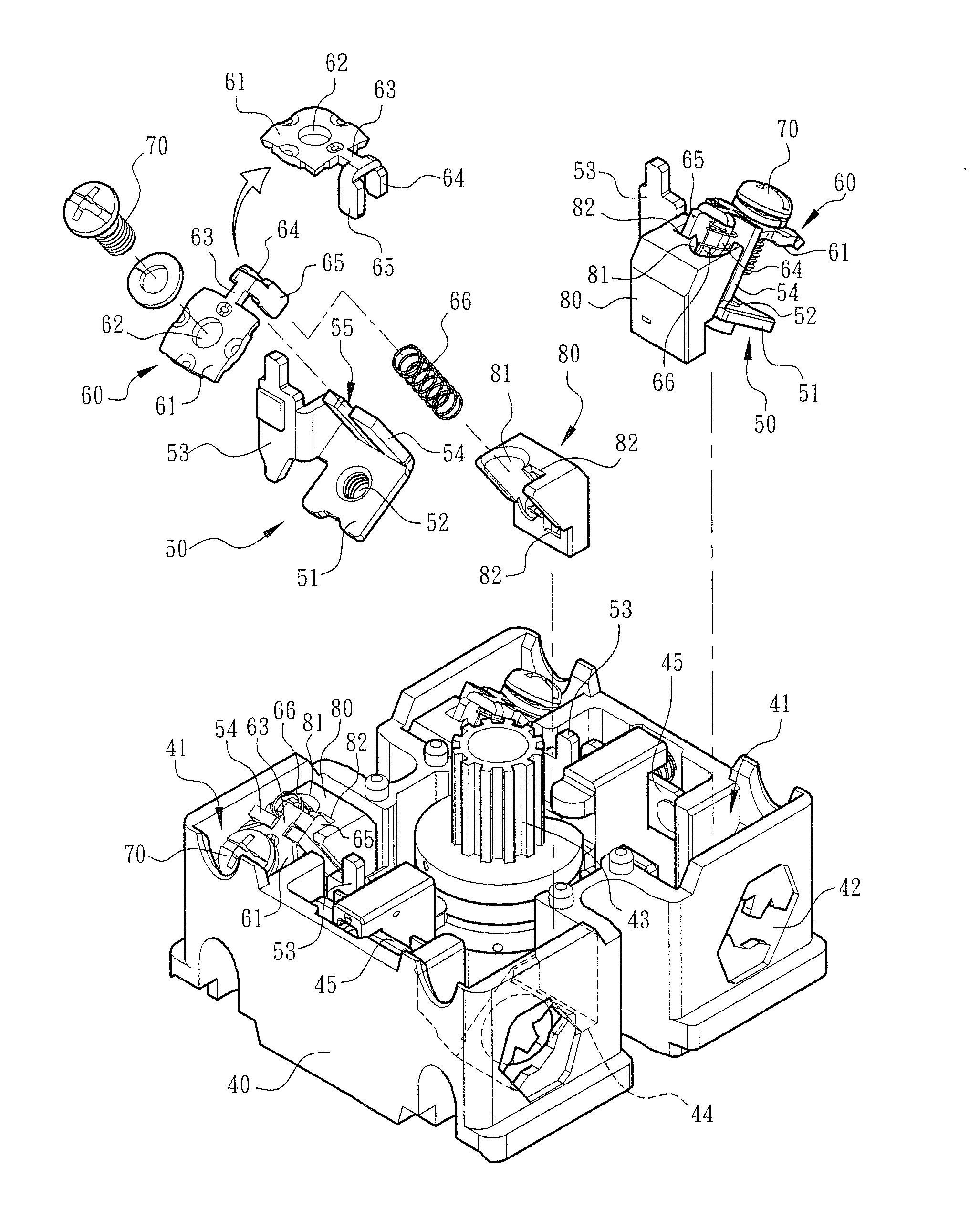
[0022]Please refer to FIGS. 4 and 5. The switch structure of the present invention includes a main body 40 made of insulation material. The main body 40 is formed with multiple cavities 41 and perforations 42 corresponding to the cavities 41 for terminal leads to insert into the cavities 41. In the cavities 41 are mounted conductive metal members 50, carrier bodies 60 assembled with the conductive metal members 50 and retainer members 70.

[0023]In this embodiment, the retainer member 70 is in the form of a screw. After the terminal lead is inserted into the cavity 41 through the perforation 42, the retainer member 70 can be operated to make the carrier body 60 press and fix the terminal lead, whereby the terminal lead is electrically connected with the conductive metal member 50. Moreover, as in the conventional operation mode, a cam 43 assembled on the main body 40 can be rotated to selectively controllably switch on / off every conductive metal member 50 mounted in the cavity 41.

[002...


PUM


Abstract

A switch structure connectable with both bare lead and flat-head terminal lead. The switch structure includes a main body formed with at least one cavity. A retainer member and a conductive metal member are arranged in the cavity for pressing the terminal lead into electrical connection with the conductive metal member. A reciprocally movable carrier body is assembled with the retainer member. The carrier body has an arm assembled with an elastic member. A restriction body is disposed in the cavity. The restriction body is formed with a chamber for receiving the arm and the elastic member of the carrier body. The restriction body restricts the moving direction or distance of the carrier body to increase the structural strength of the switch structure and enhance the lead locking ability of the switch structure.

Description

BACKGROUND OF THE INVENTION[0001]1. Field of the Invention[0002]The present invention relates generally to a switch structure design, and more particularly to an improved switch (cam) device in which a lead can be inserted and electrically connected. The switch device has a restriction body for guiding the carrier body. The switch device is applicable to both flat-head terminal lead and bare lead.[0003]2. Description of the Related Art[0004]A conventional switch or cam switch is applied to electrical engineering, electronic engineering and automatic control system for an operator to controllably switch on / off the console.[0005]The conventional switch includes an insulation housing 10 generally made of plastic material. The housing 10 is formed with multiple cavities 11 in which a conductive metal member 20, a washer 30 assembled on the conductive metal member 20 and an adjustment screw 35 are mounted. In addition, the housing 10 is formed with multiple perforations 12 corresponding ...

Claims


Application Information

Patent Timeline
Patent Type & Authority Applications(United States)
IPC IPC(8): H01H9/02
CPCH01H9/02H01H1/5855H01H9/0264H01H19/64H01R4/38
Inventor WU, CHIH-YUANHOU, SHENG-NAN
Owner SWITCHLAB
Why Eureka
Try Eureka