Airborne wind energy conversion system with endless belt and related systems and methods

a technology of airborne wind and conversion system, which is applied in the direction of electric generator control, machines/engines, mechanical equipment, etc., can solve the problems of uneconomical whole system large weight of generators carried onboard, etc., and achieve the effect of reducing energy and enhancing safety of airborne wind energy conversion system

Inactive Publication Date: 2015-01-08
GOLDSTEIN LEONID
View PDF12 Cites 17 Cited by
  • Summary
  • Abstract
  • Description
  • Claims
  • Application Information

AI Technical Summary

Benefits of technology

[0027]Another embodiment of the invention is a method of enhancing safety of an airborne wind energy conversion system, comprising steps of: attaching at least one folded parachute to a wing and / or a cable of the airborne wind energy conversion system; detecting emergency conditions, including one of the following: a) loss of control of the wind energy conversion system, b) tear down of a cable or a belt, c) breakdown of a wing, d) detachment of a wing from a cable, e) an air collision; opening the parachute on detecting the emergency conditions. The parachute allows the wing or the cable to decelerate, decreases energy, with which it hits ground, and lets any humans, who might be hit to escape. The latter function may be enhanced by using warning sound or voice in such emergency situation.

Problems solved by technology

In such conditions, the tether is subject to the very high force, requiring thick tethers and creating very large torque in the ground equipment for useful power, thus rendering the whole system uneconomical.
Among shortcomings of this method are large weight of the generator, carried onboard, large weight and limited flexibility of the tether, which is tasked with conducting electrical power from the generator to the ground.

Method used


Image

  • Airborne wind energy conversion system with endless belt and related
systems and methods
  • Airborne wind energy conversion system with endless belt and related
systems and methods
  • Airborne wind energy conversion system with endless belt and related
systems and methods

Examples


embodiments aa

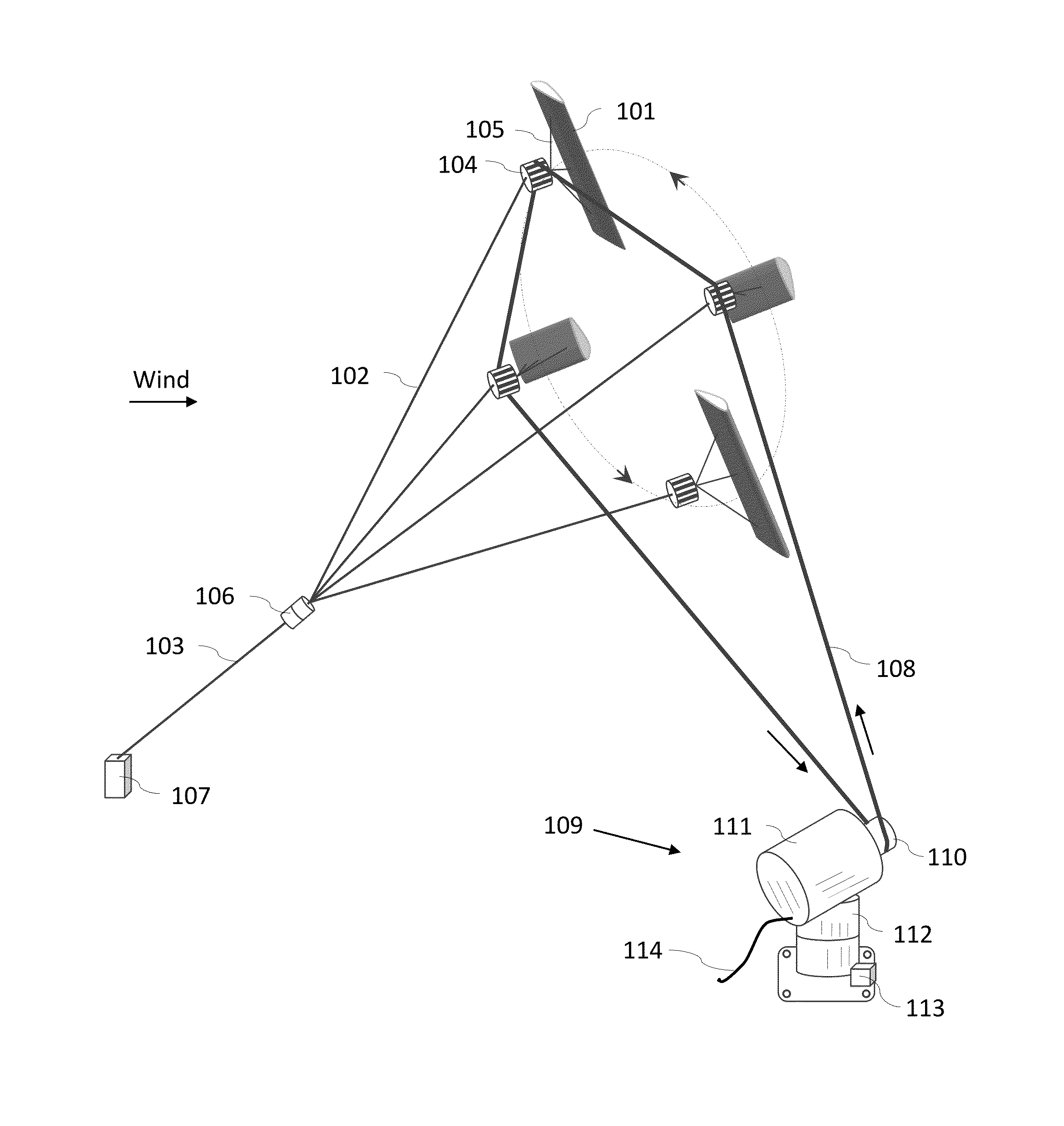
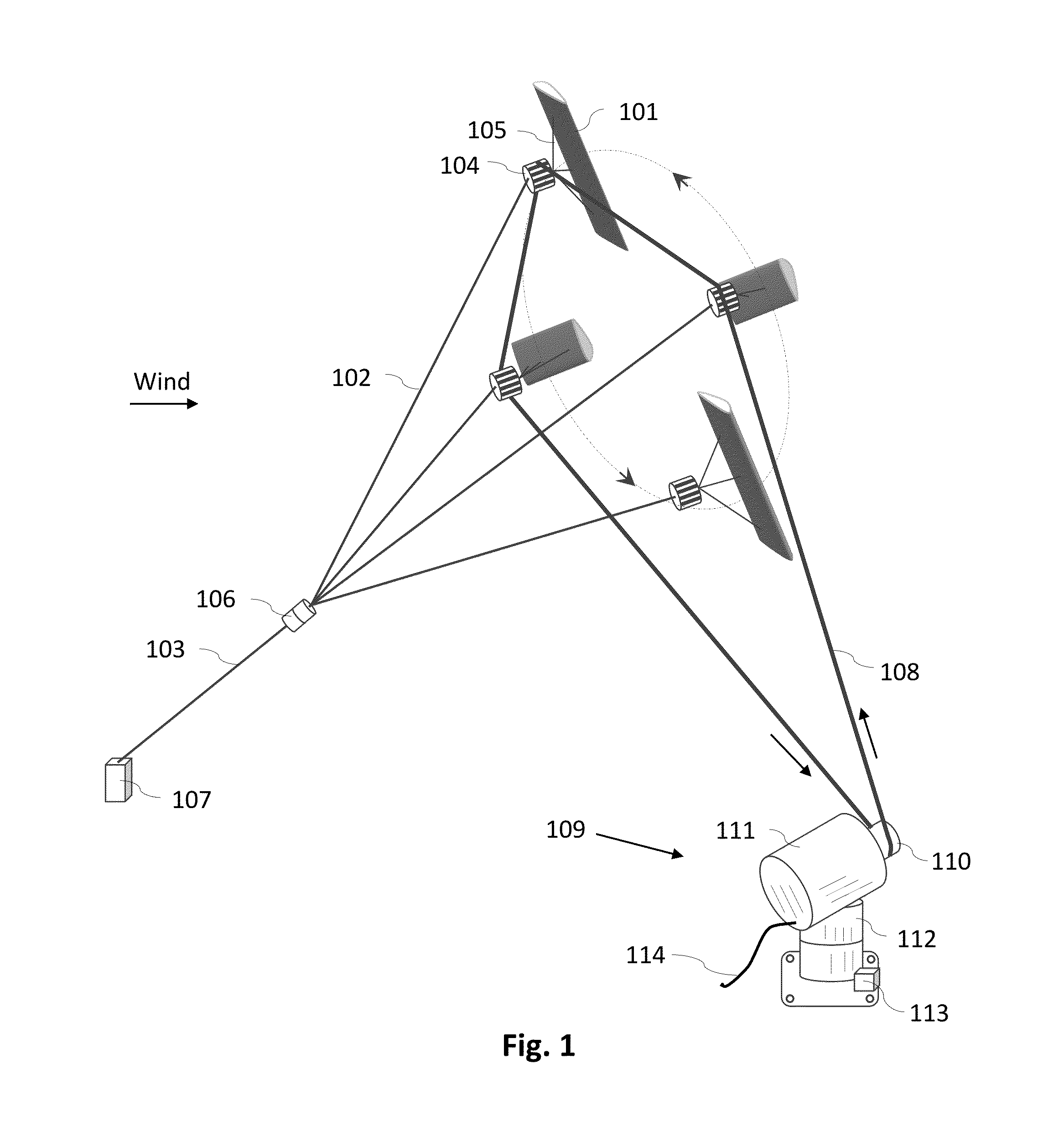
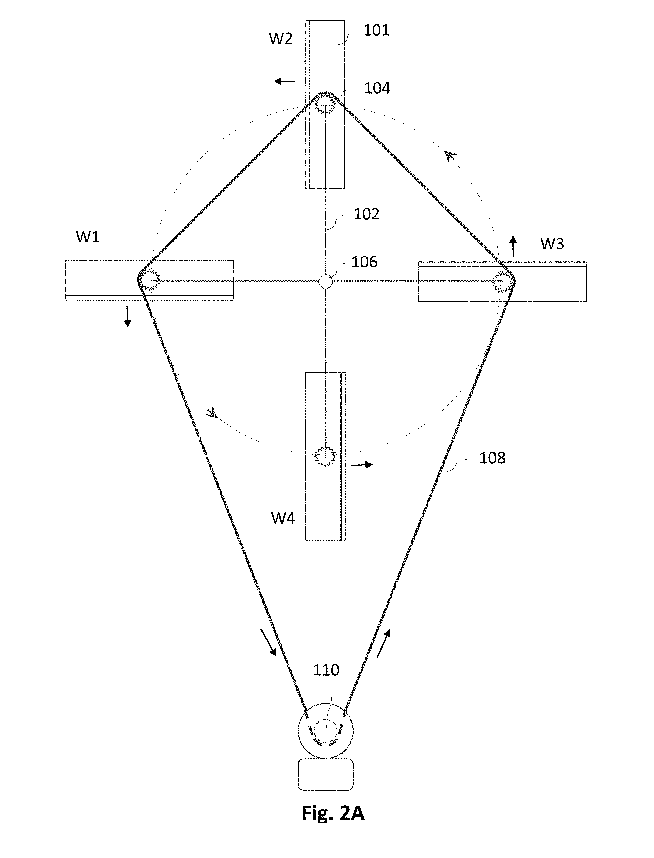
[0099]FIG. 1 shows a perspective view of one embodiment of the invention. Two or more wings 101 are placed in the air and are flying cross wind with a speed, significantly exceeding speed of the wind. FIG. 1 shows a variant of the embodiment with four wings. The trajectory of all the centers of wings 101 is the same and it is a closed curve. Each wing 101 carries a traction device 104, which is described below. Trajectory of traction devices 104 lies in a substantially one plane, or close to one plane. We will call it plane P. Traction device 104 can be attached to wing 101 directly and rigidly near wing's center or via suspension cables 105. Each wing is held by a wing cable 102, which can be attached to a traction device 104. The other side of each cable 102 is attached to a top part of an anti-twist device 106. A joint tether 103 attaches the bottom part of anti twist device 106 to a ground anchor 107. Ground anchor 107 can take form of a peg or a short tower. In time of normal w...


PUM


Abstract

Airborne wind energy conversion system with a propeller (4102) and a ground generator (4107), comprising a cross wind flying wing (4101), in which mechanical energy is transferred from the wing to the ground generator using an endless belt (4105). Another airborne wind energy conversion system, comprising a rotor, formed by freely moving wings, transferring its mechanical power to a ground based generator via a belt. The system can utilize a ribbon, connecting the wings. The belt can move continuously or reciprocally. The rotor can be axial flow, cross flow, diagonal flow or 3D flow. Related AWECS raising and landing methods are disclosed.

Description

CROSS REFERENCE TO RELATED APPLICATIONS[0001]This application is a continuation of PCT Application No. PCT / US13 / 30314, filed 12 Mar. 2013, which claims the benefit of U.S. Provisional Applications No. 61 / 621,083, filed 6 Apr. 2012, No. 61 / 657,026, filed 8 Jun. 2012, No. 61 / 662,476, filed 21 Jun. 2012, and No. 61 / 671,242, filed 13 Jul. 2012 by the same inventor as herein, the entire disclosure of which is incorporated herein by reference.BACKGROUND OF THE INVENTION[0002]This invention is generally directed to airborne wind energy conversion systems and methods. The classical work in the airborne wind energy conversion systems (AWECS) is the article by Miles L. Loyd “Crosswind Kite Power” (1979), in which the author disclosed a wind energy harvesting device, comprising a tethered wing, flying cross wind and harvesting wind energy, and transferring harvested energy to a ground based generator via motion of the tether. Crosswind motion of a wing is much more efficient, than downwind mot...

Claims


Application Information

Patent Timeline
Patent Type & Authority Applications(United States)
IPC IPC(8): F03D1/06F03D9/00
CPCF03D9/002F03D1/065F03D5/02Y02E10/70F05B2240/921F03D15/00F03D9/25Y02E10/728Y02E10/72F03D15/10F03D13/20
Inventor GOLDSTEIN, LEONID
Owner GOLDSTEIN LEONID
Why Eureka
Try Eureka