Synchronous electric machine

a technology of electric motors and synchronous motors, applied in the direction of synchronous motors, electric generator control, association for rectification, etc., can solve the problems of high relative cost of exciter, high manufacturing cost of synchronous motors, and inability to provide any means for controlling the rotor, so as to improve the performance of the machine

Inactive Publication Date: 2015-01-08
GENRH8
View PDF5 Cites 6 Cited by
  • Summary
  • Abstract
  • Description
  • Claims
  • Application Information

AI Technical Summary

Benefits of technology

[0024]According to a further embodiment of the invention, capacitors are added to at least two rotor terminals so as to provide filtering or control actions to improve the performance of the machine.

Problems solved by technology

Although the efficiency of a synchronous motor is generally higher than for other industrial electric motor types, synchronous motors are generally complex and expensive to manufacture—largely related to their requirement for a rotating exciter to vary rotor field current.
Permanent magnet synchronous motors are simple and less expensive but do not provide any means for controlling the rotor field excitation, which is fixed by the permanent magnets on the rotor.
In general, the smaller the generator, the higher the relative cost of the exciter.

Method used


Image

  • Synchronous electric machine
  • Synchronous electric machine
  • Synchronous electric machine

Examples


first embodiment

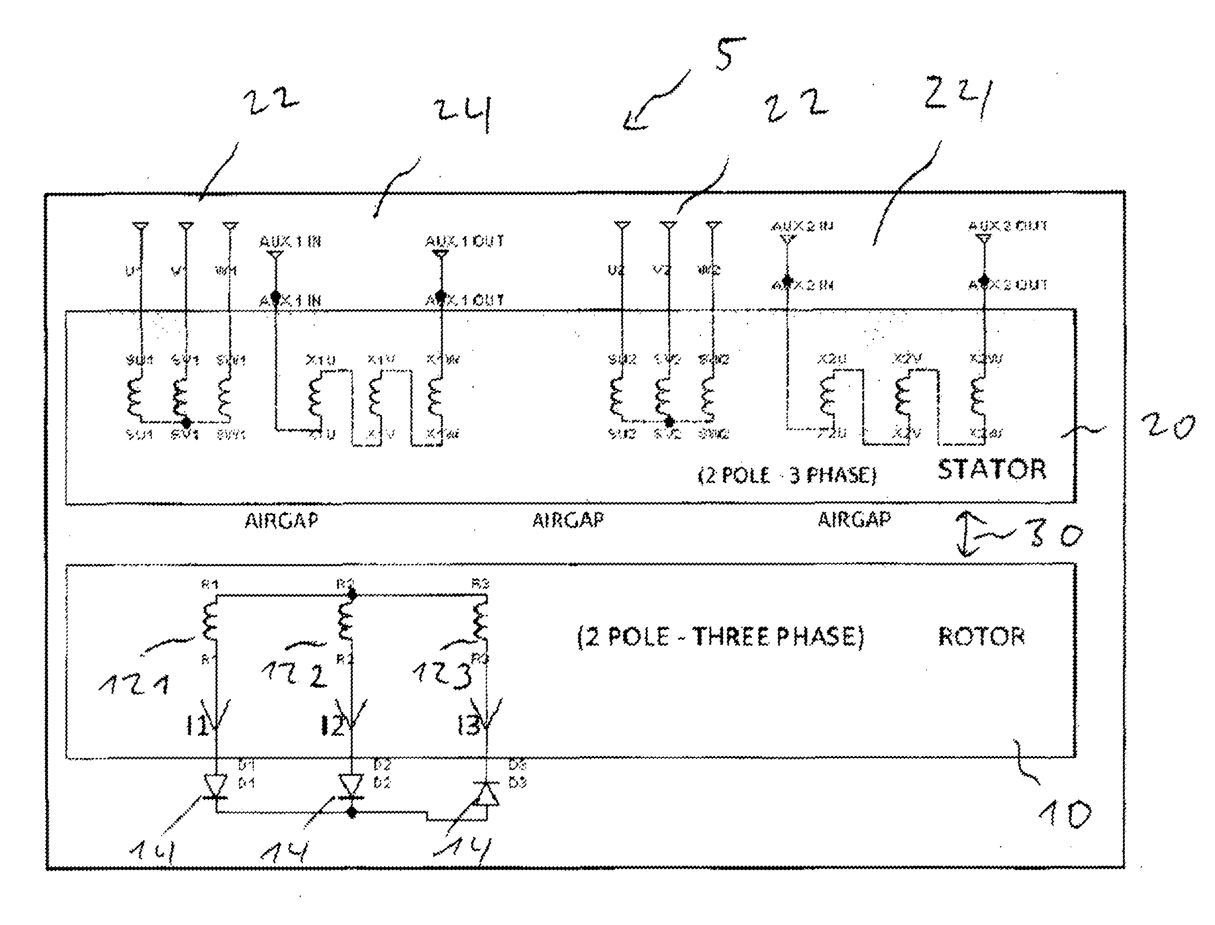
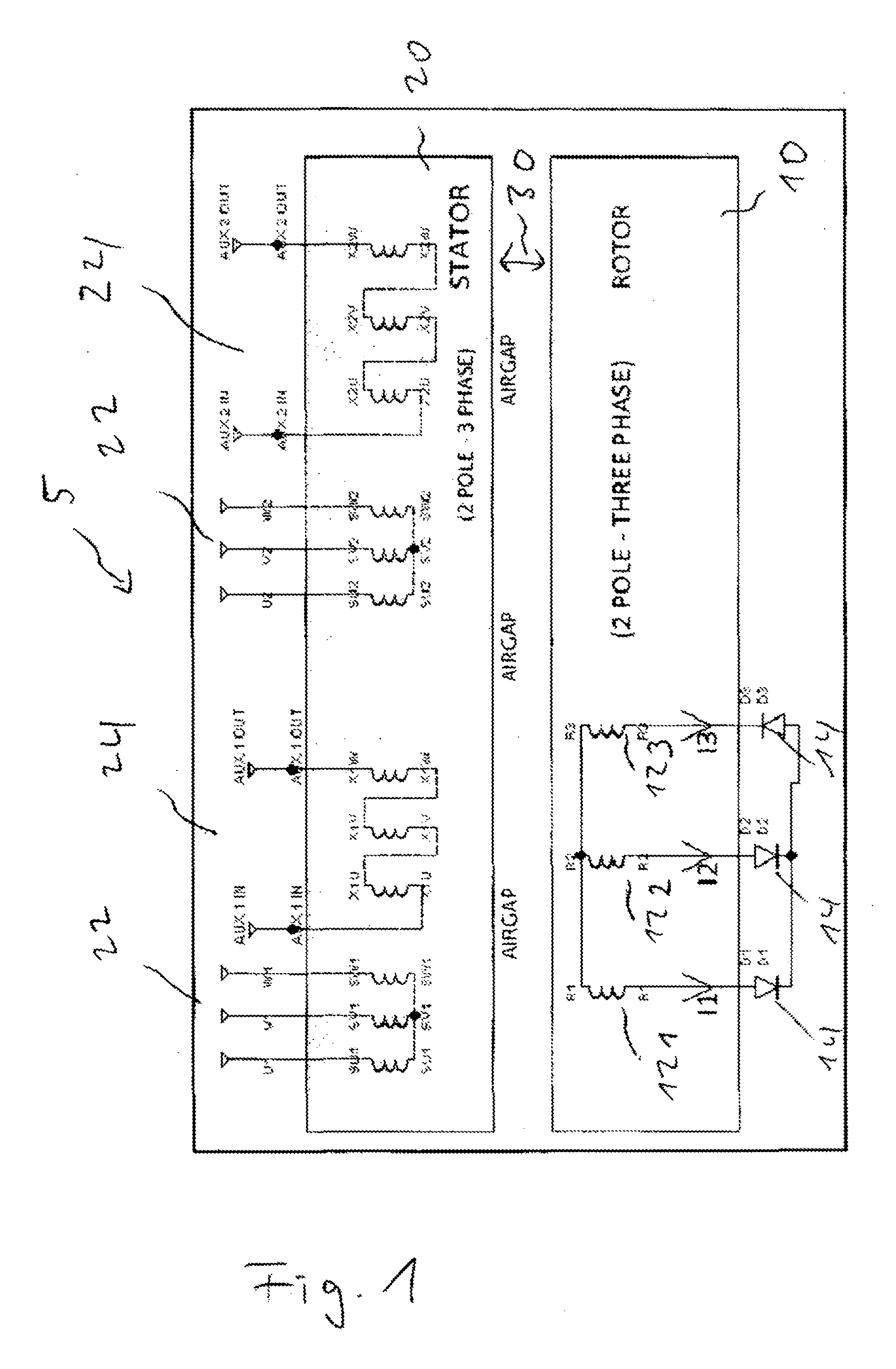
[0040]Making now reference to FIG. 1, the invention is shown as a schematic diagram. The electrical machine 5 includes a rotor 10. The rotor 10 includes a multi-phase and multi-pole set of rotor windings 12. As depicted in FIG. 1, there are three phases present, which are generated by the three windings 121, 122 and 123. Two of the three windings 121 and 122 are connected in parallel and one winding 123 in an opposite direction of diodes 14 thus generating two poles. The rotor winding 12 is simplified here to illustrate an uneven current distribution through each of the three rotor phases. Current 13 through the one diode 14 associated to winding 123 will be equal to the (negative) sum of I1 and I2, meaning that this winding phase will have to carry twice the current that the other two phases carry.

[0041]The stator 20 is a three-phase multi-pole arrangement with two sets of main windings 22 each having three coils 221, 222 and 223 for the three phases and two sets of auxiliary windi...

second embodiment

[0057]In a second embodiment, the excitation of the rotor 10 can be achieved by injecting alternating current into the stator 20. In the same way as a direct current superimposed on the stator 20 via the neutral conductor can excite the rotor 10, an alternating current (AC) can be used as well. This will also be implemented in the same way as described above, by injecting current into the neutral conductor. This embodiment is more suitable for a motor than a generator and will greatly improve motor performance at lower speeds.

[0058]In a second embodiment, the auxiliary windings 24 can be excited with AC or DC. Although DC will be best for generators and AC for motors—both are included as embodiments for both motors and generators.

[0059]The multi-phase or poly-phase rotor winding 12, and cylindrical rotor construction allows much smoother rotor field current than in any other single-phase implementations, effectively allowing DC to be used in the auxiliary windings 24, without a sign...


PUM


Abstract

This invention relates to a synchronous electric machine including a stator and a rotor, wherein the stator includes a multi-pole stator winding set, the rotor includes a multi-pole cylindrical rotor design or salient pole design with at least two-phase rotor winding set on the cylindrical rotor having the same number of poles as the stator, and the stator windings provide excitation to the rotor by means of stator current imbalance or superimposition, by secondary windings to produce harmonic flux or by a three-phase winding with an external source of excitation. Furthermore, the invention relates to a method for operating a synchronous electric machine.

Description

FIELD OF THE INVENTION[0001]This invention relates to a synchronous electric machine. More particularly, this invention relates to a controllable-field synchronous electric machine which can be used as a synchronous generator or as a synchronous motor. Furthermore, the invention relates to a method for operating a synchronous electric machine.BACKGROUND TO THE INVENTION[0002]It is known in the art that a synchronous electric machine can be used both as a motor and as a generator. While the electric motor is usually described in terms of mechanical terms, i.e. stator and rotor, the electric generator is described from an electrical point of view, i.e. in terms of armature and field. Although different terminology exists, synchronous electric machines can perform bath tasks and are in the following referred to as an electric machine.[0003]The majority of industrial electric motors in use today are asynchronous (induction) types. This is mainly due to the fact that asynchronous motors ...

Claims


Application Information

Patent Timeline
Patent Type & Authority Applications(United States)
IPC IPC(8): H02K11/04H02K19/26H02K19/36H02K3/28H02K19/12
CPCH02K11/044H02K11/046H02K19/26H02K19/12H02K19/36H02K3/28H02K19/28H02P9/302H02P25/03H02P27/02
Inventor HERBERT, RUSSELLMELAIA, ROBERT
Owner GENRH8
Why Eureka
Try Eureka