Laser beam machining method and laser beam machining apparatus

a laser beam and machining method technology, applied in metal working equipment, manufacturing tools, welding/soldering/cutting articles, etc., can solve the problems of insufficient improvement of machining ability and difficulty in so as to achieve high machining ability, the effect of increasing the pulse width of ultraviolet laser beams and significantly improving machining ability

Inactive Publication Date: 2007-09-20
MITSUBISHI MATERIALS CORP
View PDF12 Cites 19 Cited by
  • Summary
  • Abstract
  • Description
  • Claims
  • Application Information

AI Technical Summary

Benefits of technology

[0027] That is, according to the laser beam machining method and laser beam machining apparatus related to the invention, in grooving and cutting a semiconducting material or a ceramic material, as the machining depth is greater or as the scanning speed is higher, the pulse width of an ultraviolet laser beam is set to be greater. As a result, the machining ability can be significantly improved compared with a case where the average power is increased. Accordingly, deep machining can be efficiently performed even in these materials by virtue of high machining ability, and the scanning speed of a laser beam can be enhanced. As a result, the machining productivity can be improved considerably.

Problems solved by technology

However, it was difficult to improve the machining ability significantly compared with cases where an organic material, such as a resin material, and metals, are machined.
That is, if the pulse width of an ultraviolet laser beam is less than 15 nsec, the machining ability cannot be improved sufficiently.

Method used


Image

  • Laser beam machining method and laser beam machining apparatus
  • Laser beam machining method and laser beam machining apparatus
  • Laser beam machining method and laser beam machining apparatus

Examples


examples

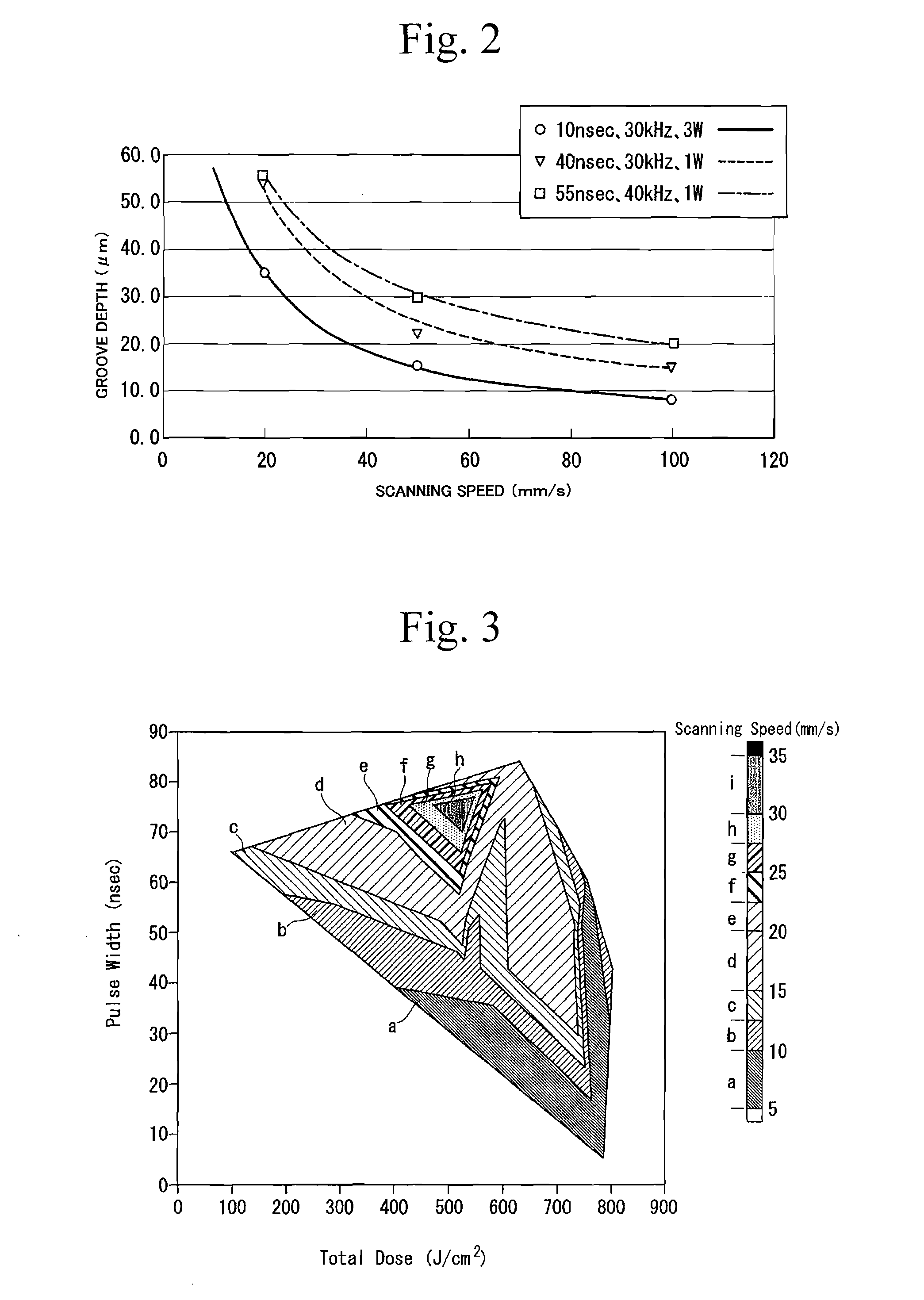
[0056] In the laser beam machining according to the invention, the machining ability in a case where grooving was actually performed on an alumina substrate was investigated.

[0057] In this Example, as shown in Table 1, machining was performed by changing the scanning speed to 20, 50, and 100 mm / s to change the groove depth.

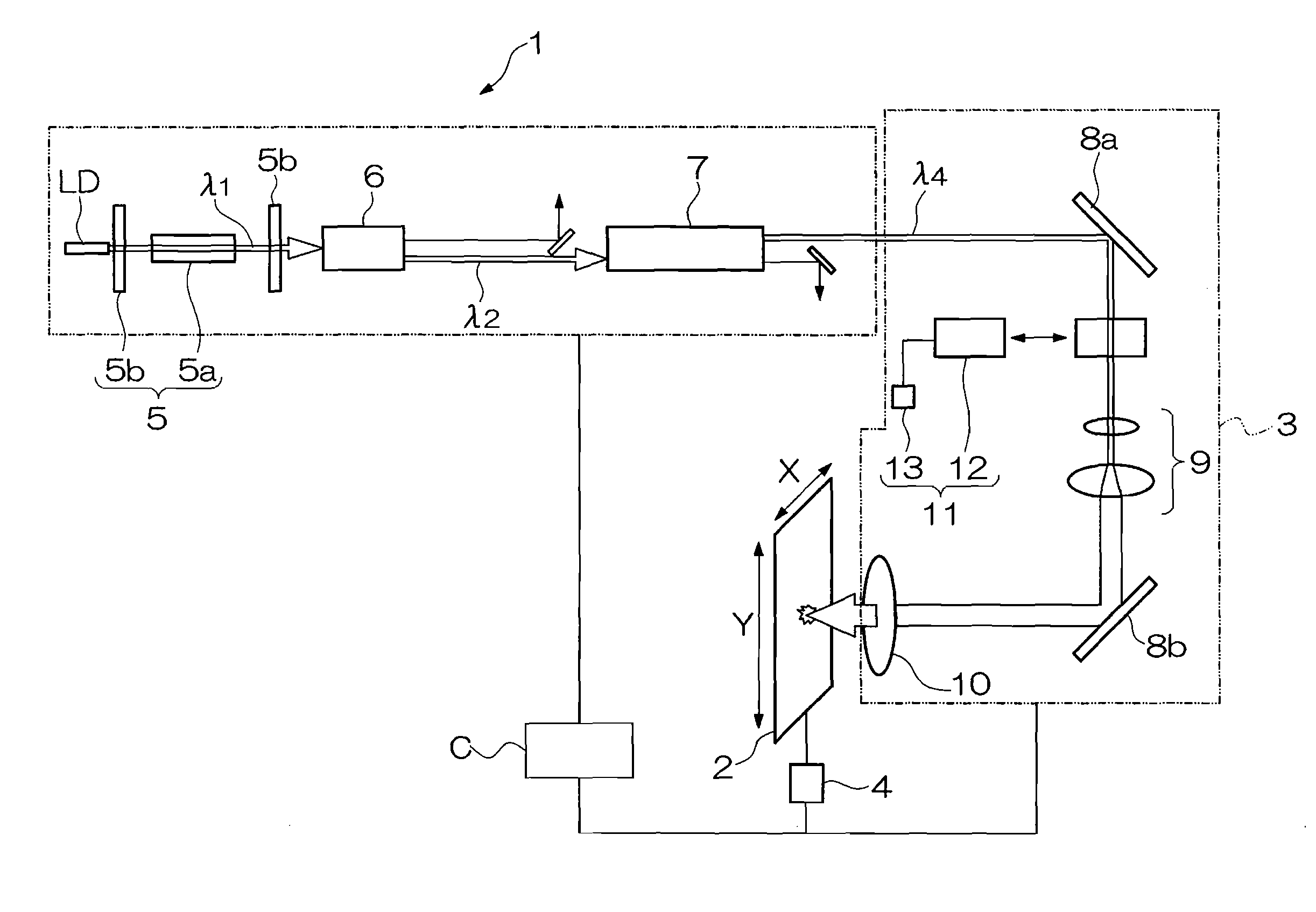
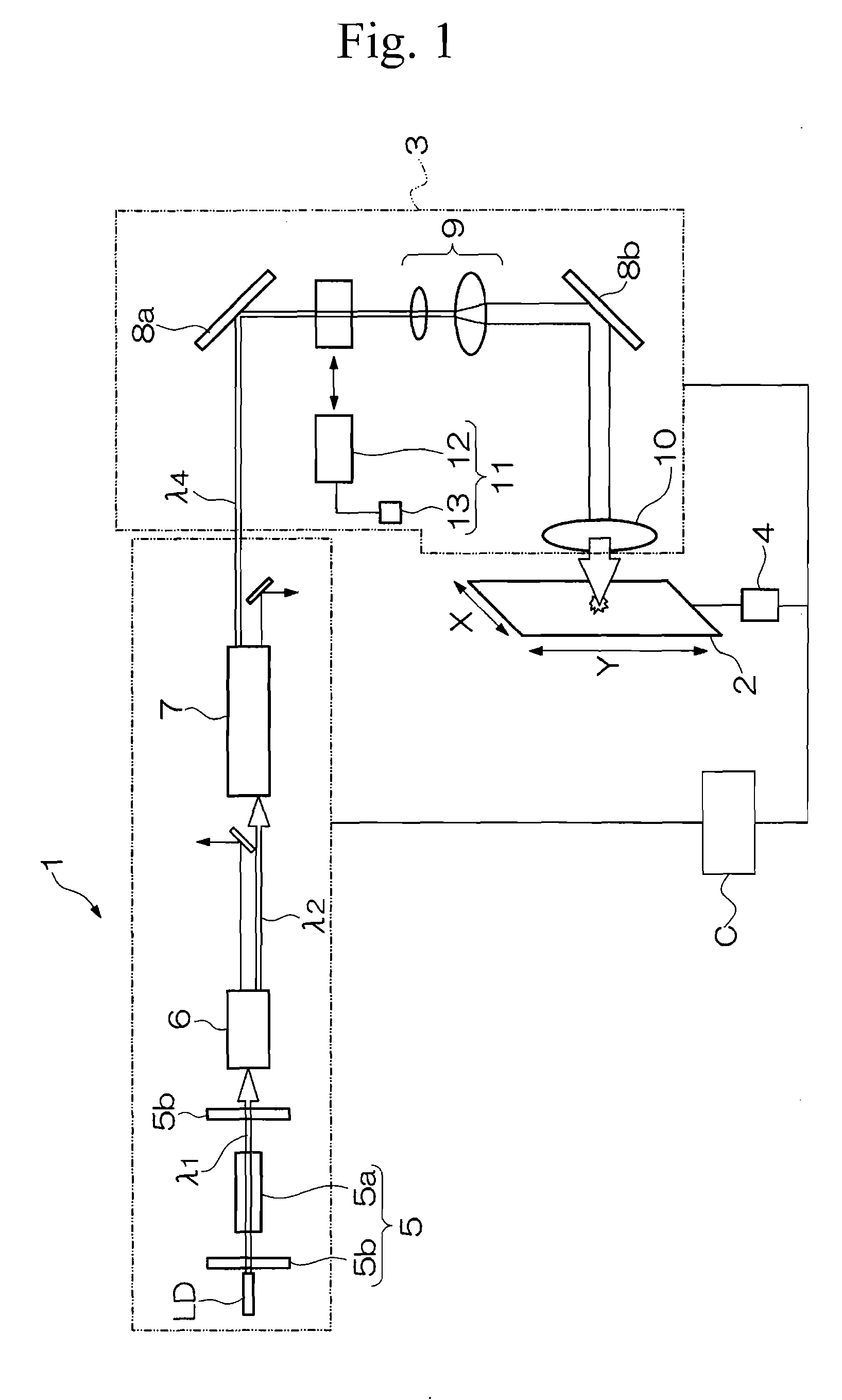
[0058] As the machining conditions, Example (1) in which the pulse width, the frequency, and the average power were set to 40 nsec, 30 kHz, and 1 W, respectively, and Example (2) in which the pulse width, the frequency, and the average power were set to 55 nsec, 40 kHz, and 1 W, respectively, were investigated. In addition, as conventional machining conditions, Comparative Example in which the pulse width, the frequency, and the average power were set to 10 nsec, 30 kHz, and 3 W, respectively, was investigated. The results thereof are shown in Table 1 and FIG. 2. In addition, the number of times of traces is set to two times in any of the above Examples.

TABLE ...


PUM

PropertyMeasurementUnit
wavelengthaaaaaaaaaa

Abstract

In a laser beam machining method and a laser beam machining apparatus, a higher improvement in machining ability is required for grooving and cutting of a semiconducting material or a ceramic material. In order to meet this requirement, the invention provides a laser beam machining apparatus and a laser beam machining method in which an ultraviolet laser beam is irradiated in pulses onto a workpiece made of an inorganic material to groove or cut the workpiece. In this laser beam machining apparatus and laser beam machining method, as the scanning speed of the ultraviolet laser beam is higher, or as the machining depth of the grooving or the cutting is greater, the pulse width of the ultraviolet laser beam is set to be greater. This can significantly improve the machining ability compared with a case where the average power is increased.

Description

CROSS REFERENCE TO PRIOR APPLICATIONS [0001] This is a U.S. national phase application under 35 U.S.C. § 371 of International Patent Application No. PCT / JP2005 / 017943 filed Sep. 29, 2005, and claims the benefit of Japanese Applications No. 2004-283454 filed Sep. 29, 2004 and 2005-274157 filed Sep. 21, 2005 all of which are incorporated by reference herein. The International Application was published in Japanese on Apr. 6, 2006 as International Publication No. WO 2006 / 035870 under PCT Article 21 (2).TECHNICAL FIELD [0002] The present invention relates to a laser beam machining method and a laser beam machining apparatus which are suitable for grooving or cutting of a semiconducting material, a ceramic material, etc. BACKGROUND ART [0003] In recent years, a laser beam machining technique using a ultraviolet-ray laser capable of high-precision machining is adopted for grooving (scribing) and cutting of resin substrates, metallic plates, ceramics plates, and semiconductor wafers. [0004]...

Claims


Application Information

Patent Timeline
Patent Type & Authority Applications(United States)
IPC IPC(8): B23K26/38B23K26/40
CPCB23K26/408B28D5/00B28D1/221B23K2201/40B23K26/40B23K2101/40B23K2103/52
Inventor KATO, HIROKAZUHIGANO, SATORU
Owner MITSUBISHI MATERIALS CORP
Why Eureka
Try Eureka