

Recording apparatus
- Summary
- Abstract
- Description
- Claims
- Application Information
AI Technical Summary
Benefits of technology
Problems solved by technology
Method used
Image

Examples
examples
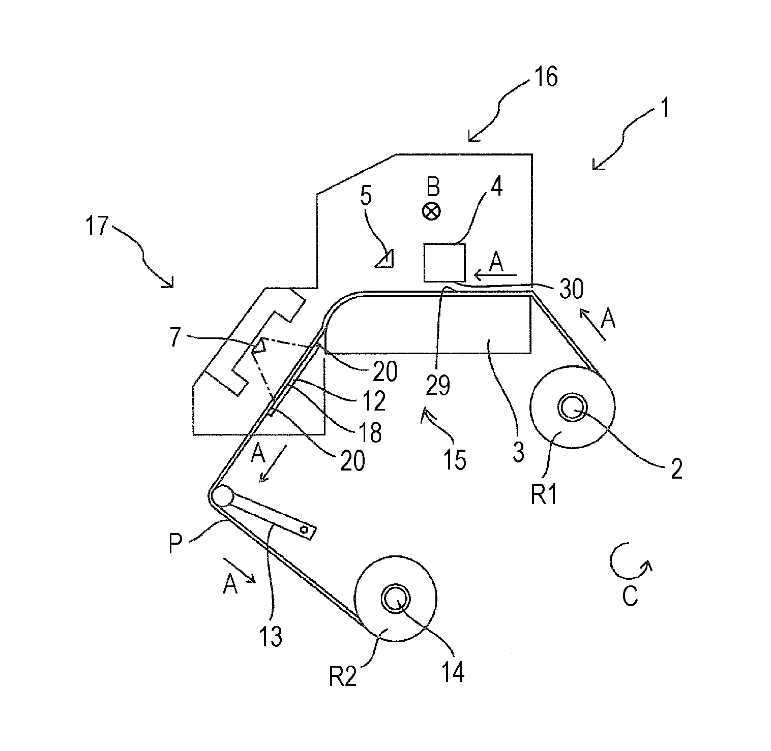
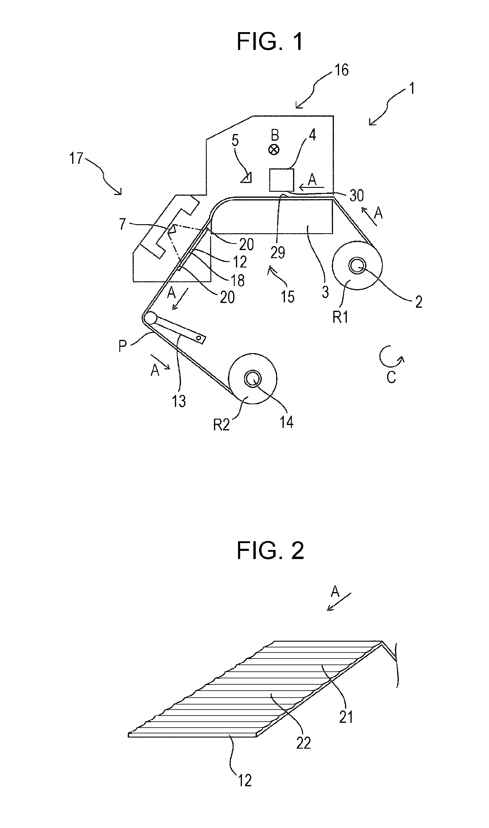
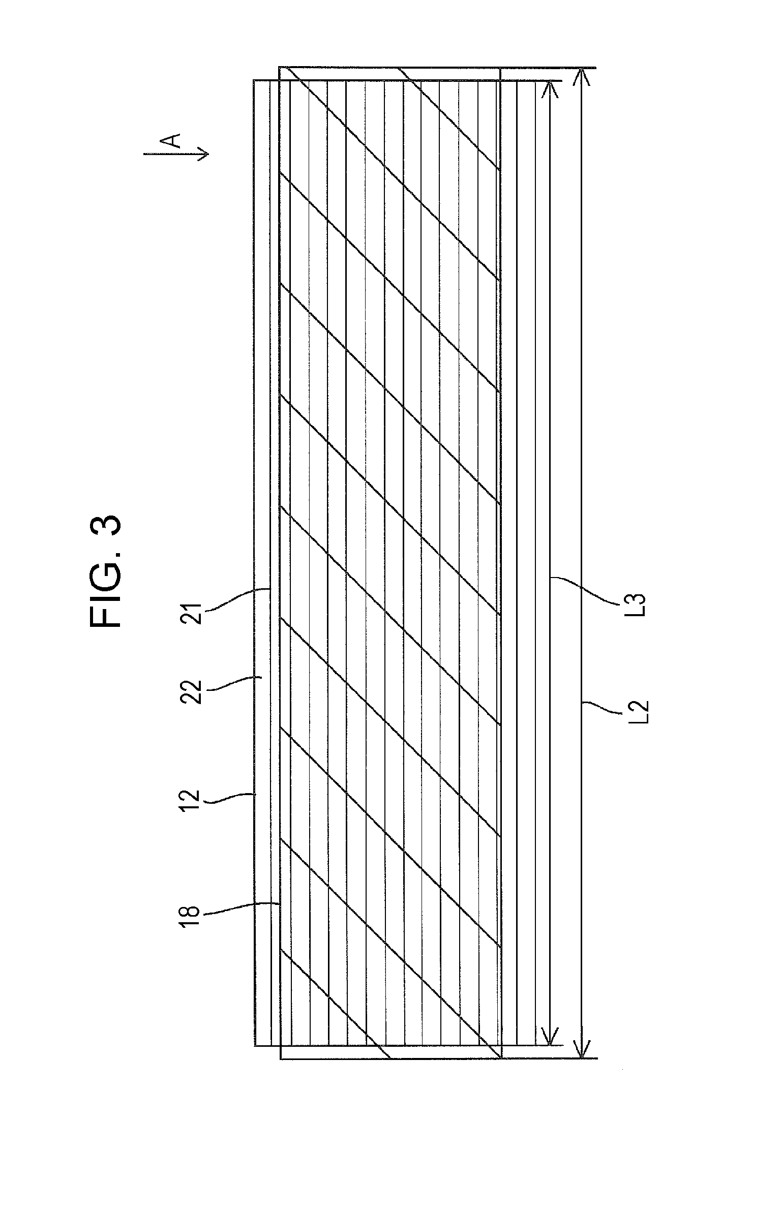
[0076]The medium supporting portion 12 of the recording apparatus 1 in the embodiment was formed by each of constituent materials in Examples 1 to 7 and Comparison Examples 1 and 2 in the following Table 1. Presence and absence of generation of condensation and warpage (thermal deformation) of the medium supporting portion 12 when the intensity of the electromagnetic wave irradiation was adjusted such that the medium supporting portion 12 was 60° C., 80° C., or 120° C. were evaluated.
[0077]The following Table 1 indicates the constituent materials, the thermal conductivities, the heat resistant temperatures (ASTM D-648 test method), and the above-mentioned evaluation results in Examples 1 to 7 and Comparison Examples 1 and 2.
[0078]The evaluation standards for the presence and absence of the generation of the condensation and the warpage of the medium supporting portion (deformation by softening due to low heat resistant temperature) are as follows and the unevaluated items are indica...
PUM
 Abstract
Description
Claims
Application Information