Controlling Radio Measurements of a User Equipment within a Cellular Network System

a radio measurement and user equipment technology, applied in the field of cellular networks, can solve the problem of not being able to configure two or more measurement objects, and achieve the effect of enhancing the measurement configuration and related measurements, maximizing mobility performance, and maximizing the measurement configuration

Active Publication Date: 2015-01-08
NOKIA SOLUTIONS & NETWORKS OY
View PDF9 Cites 38 Cited by
  • Summary
  • Abstract
  • Description
  • Claims
  • Application Information

AI Technical Summary

Benefits of technology

[0013]However, the common systems may provide some disadvantages. Considering the intra-frequency case, when the UE performs measurements towards different cell types, only one measurement configuration is possible. Therefore measurements are limited and not providing flexibility towards different cell types in various heterogeneous network deployments. It is not possible to configure more than one mobility related measurement parameter (for instance TTT, t-Reselection, Qhyst) value per measurement object. The Mobility State Estimation can scale down for example the TTT value in RRC connected mode by factors [0.25, 0.50, 0.75, 1.00], which can make the fast moving UEs to enter small power cells even faster. However, as already explained above, this is not desired. Non-stationary, irregular and / or unpredictable trajectory of users can increase the need for diverse measurement configurations. When only one measurement object is possible for a given frequency, it means that in order to support mobility through a heterogeneous network area, several measurement configurations or reconfigurations needs to be signalled to UE for optimum mobility performance.
[0014]The idea of the herein described method is to enhance the measurement configuration and related measurements. The method provides a flexibility to the measurements and can enable support for advanced mobility scenarios especially in areas where heterogeneous networks are deployed.
[0016]The described method relates in particular to LTE rel. 11+ and in particular to HetNet measurements, but is not limited to these environments. The described method provides a way to enhance the measurement configuration and related measurements so that different target cell types can be supported with optimized measurement parameters improving the mobility in HetNets. The basic idea is that a UE will be provided with different measurement configuration for different cell types (or at least one for macro cell and another one for small cells).
[0020]According to this embodiment, after receiving the radio measurement configuration, the UE may be configured in such a way to apply specific parameters for specific radio measurements for specific cell type characteristics. With one radio measurement configuration, the UE may be configured to apply different kind of measurements (i.e., using different parameters), for different cell type characteristics. This may provide a greater flexibility without a need of a complete reconfiguration.
[0033]The UE may have a pre-knowledge about all neighboring cells, including the at least one further cell, based on a neighbour cell list along with cell type characteristics of those cells. This may allow better control of when and how often radio measurements are reported for different type of cells which in turn may allow control of when the UE is handover to a target cell of a specific cell type. This in essence may allow avoiding high speed UEs in small cells which might be important for Hetnet deployment involving macro and small cells.
[0037]The UE may take also into account its own classification state when starting radio measurements. This may further improve the flexibility and accuracy of radio measurements.

Problems solved by technology

E-UTRAN only configures a single measurement object for a given frequency, i.e. it is not possible to configure two or more measurement objects for the same frequency with different associated parameters, e.g. different offsets and / or blacklists.

Method used


Image

  • Controlling Radio Measurements of a User Equipment within a Cellular Network System
  • Controlling Radio Measurements of a User Equipment within a Cellular Network System
  • Controlling Radio Measurements of a User Equipment within a Cellular Network System

Examples


Embodiment Construction

[0067]In the following, embodiments of the herein disclosed subject matter are illustrated with reference to the drawings and reference to aspects of current standards, such as LTE. However, such reference to current standards is only exemplary and should not be considered as limiting the scope of the claims.

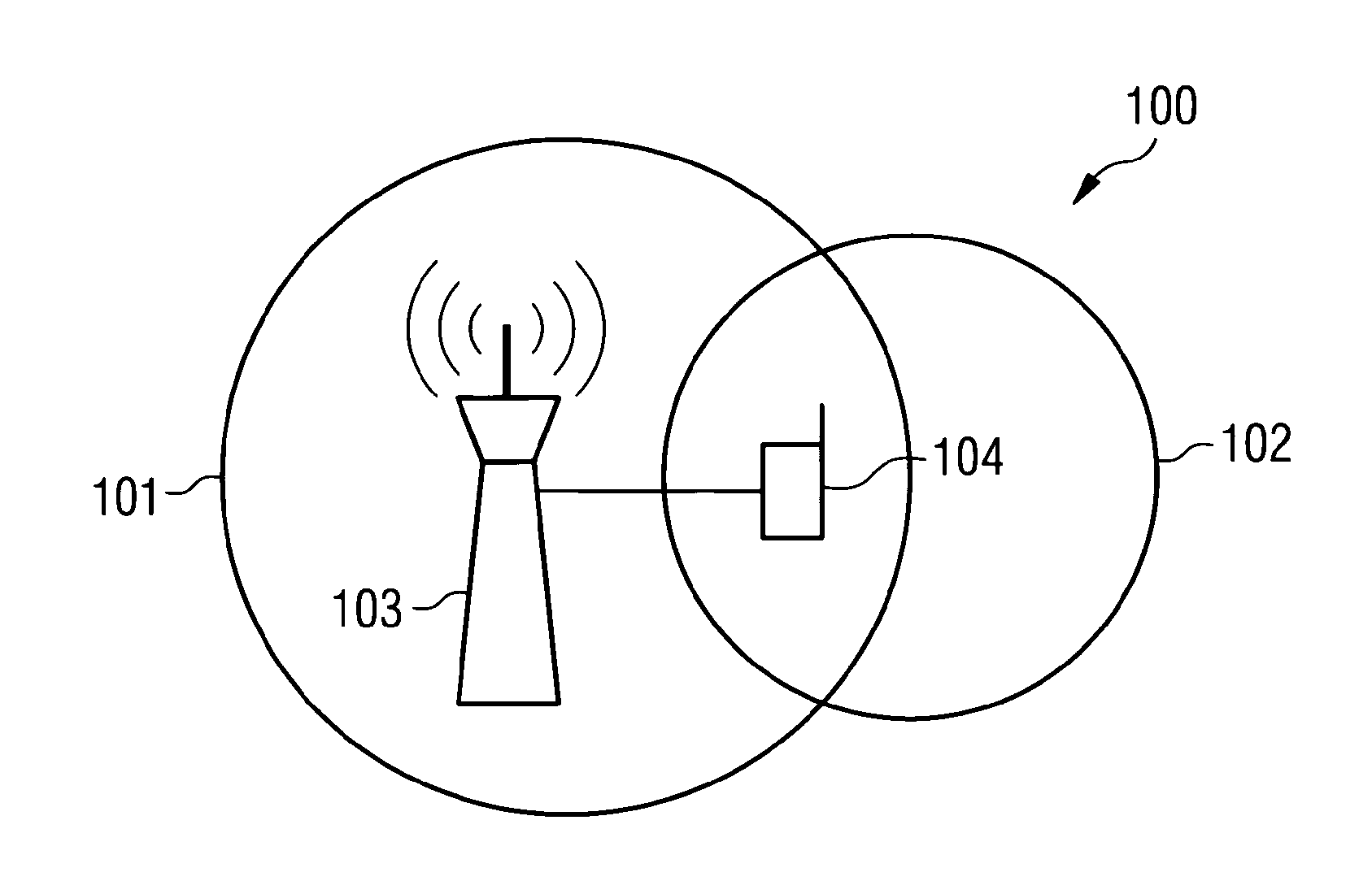
[0068]FIG. 1 shows a cellular network system 100. A user equipment 104 is served by and located in a cell 101. The cell 101 has a first cell type characteristic. The cell 101 is served by a (serving) base station 103. The cell 101 may also be called “source cell”. The cellular network system comprises at least one further cell 102. The at least one further cell 102 has a second cell type characteristic. The at least one further cell 102 is neighbored to the cell 101 and may be the target cell for a handover. The base station 103 provides a radio measurement configuration to the user equipment 104. The radio measurement configuration is indicative for parameters to be applied by ...


PUM


Abstract

It is described a method for controlling radio measurements of a user equipment within a cellular network system, wherein the user equipment is served by a cell of a first cell type characteristic, the cell being assigned to a base station, wherein the cellular network system includes the cell and at least one further cell of a second cell type characteristic. The method includes providing, by the base station, a radio measurement configuration to the user equipment, wherein the radio measurement configuration is indicative for parameters to be applied by the user equipment for radio measurements, the radio measurement configuration includes different parameters being assigned to different cell type characteristics, and controlling the radio measurements of the user equipment based on the provided radio measurement configuration.

Description

FIELD OF INVENTION[0001]The present invention relates to the field of cellular networks and in particular to heterogeneous networks.ART BACKGROUND[0002]Cellular network systems may be arranged in multi-layer cellular systems—also referred to as heterogeneous networks (HetNet). In this context, multi-layer refers to cases with a mixture of macro base stations and small power base stations (for instance pico and micro). Macro-layer and pico / micro layer may also be implemented in different radio access technologies (RAT), for example GSM macro layer and LTE micro layer.[0003]In such networks, a user equipment (UE) may use a measurement configuration. A measurement configuration defines how the UE will experience its environment and acts as an input to mobility management in connected mode (connected to a base station for an active communication) and autonomously in idle mode (without active communication). Typically, the Physical Cell Identity (PCI) is used to identify a cell for the r...

Claims


Application Information

Patent Timeline
Patent Type & Authority Applications(United States)
IPC IPC(8): H04W36/00
CPCH04W36/0088H04W24/10H04L67/1053H04W36/0094H04W24/02H04W84/18
Inventor SAILY, MIKKOMICHAELSEN, PER HENRIKBARBERA, SIMONE
Owner NOKIA SOLUTIONS & NETWORKS OY
Why Eureka
Try Eureka