Photovoltaic system

a photovoltaic system and photovoltaic module technology, applied in the direction of power supply testing, process and machine control, instruments, etc., can solve the problems of damage to the inverter positioned at the next stage of the photovoltaic module, the conventional photovoltaic system, etc., and achieve the effect of minimizing nois

Active Publication Date: 2015-01-15
LSIS CO LTD
View PDF1 Cites 9 Cited by
  • Summary
  • Abstract
  • Description
  • Claims
  • Application Information

AI Technical Summary

Benefits of technology

[0008]Therefore, an aspect of the detailed description is to provide a photovoltaic system capable of minimizing noise occurring while a maximum power point tracking (MPPT) algorithm is performed, by bypassing one or more photovoltaic modules among a plurality of photovoltaic modules serially-connected to each other, in a case where the corresponding photovoltaic module has a significant change in the amount of sunshine, i.e., in a case where an output current of the corresponding photovoltaic module is significantly decreased due to wind, rain, dust in the air, shading, etc. For this, a present output current and a previous output current of the corresponding photovoltaic module are compared with each other. Then if a difference between the present output current and the previous output current exceeds a preset reference value, the corresponding photovoltaic module is bypassed.

Problems solved by technology

However, the conventional photovoltaic system may have the following problems.
When an output power of one of the plurality of photovoltaic modules is drastically decreased, noise occurs during a process of searching for (tracking) a maximum power of a plurality of photovoltaic modules connected to each other in series.
In this case, an inverter positioned at the next stage of the photovoltaic modules may be damaged.

Method used


Image

  • Photovoltaic system
  • Photovoltaic system
  • Photovoltaic system

Examples


Embodiment Construction

[0026]Description will now be given in detail of the exemplary embodiments, with reference to the accompanying drawings. For the sake of brief description with reference to the drawings, the same or equivalent components will be provided with the same reference numbers, and description thereof will not be repeated.

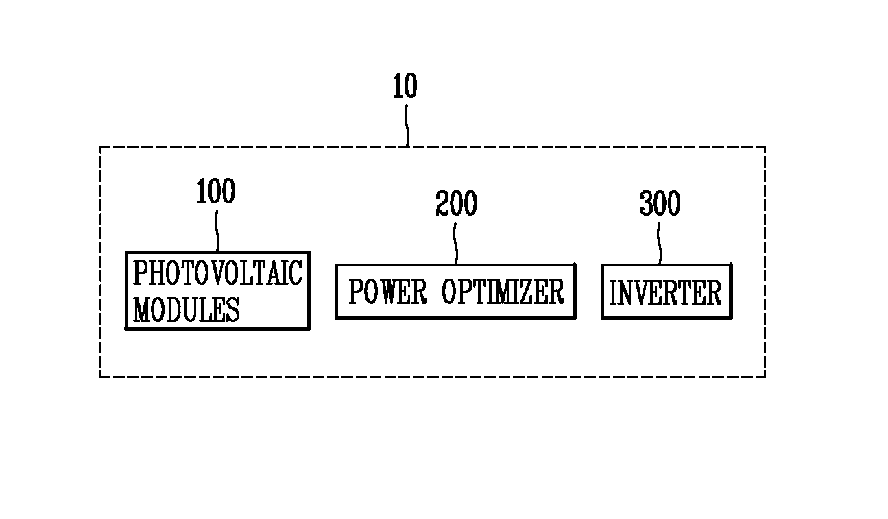
[0027]FIG. 1 is a block diagram illustrating a configuration of a photovoltaic system 10 according to the present invention.

[0028]As shown in FIG. 1, the photovoltaic system 10 includes a photovoltaic module 100, a power optimizer 200 and an inverter 300. However, the present invention is not limited to the components of FIG. 1. That is, the photovoltaic system 10 may include smaller or larger number of components than the components shown in FIG. 1.

[0029]The photovoltaic module 100 is formed in plurality, and the plurality of photovoltaic modules 100 are formed in series (or are implemented in a string).

[0030]The photovoltaic modules 100 generate electricity from solar li...


PUM


Abstract

Disclosed is a photovoltaic system including a power optimizer, capable of minimizing noise occurring due to shading, an error in an output power of a photovoltaic module, etc. while a maximum power point tracking (MPPT) algorithm is performed. The photovoltaic system includes a photovoltaic module; a power optimizer; and an inverter, wherein the power optimizer includes: an input unit configured to receive an output power of the photovoltaic module; a sensing unit configured to sense an output voltage and an output current of the photovoltaic module; and a controller configured to control an output of the power optimizer, by comparing the presently-sensed current with a previously-sensed current.

Description

CROSS-REFERENCE TO RELATED APPLICATION[0001]Pursuant to 35 U.S.C. §119(a), this application claims the benefit of earlier filing date and right of priority to Korean Application No. 10-2013-0081154, filed on Jul. 10, 2013, the contents of which are all hereby incorporated by reference herein in its entirety.BACKGROUND OF THE DISCLOSURE[0002]1. Field of the Disclosure[0003]The present disclosure relates to a photovoltaic system, and particularly, to a photovoltaic system including a power optimizer, capable of minimizing noise occurring while a maximum power point tracking (MPPT) algorithm is performed, due to shading, an error in an output power of a photovoltaic module, etc.[0004]2. Background of the Disclosure[0005]Generally, a photovoltaic system includes a plurality of photovoltaic modules connected to each other in series, and an inverter configured to convert a DC voltage output from the plurality of photovoltaic modules into an AC voltage, and configured to output the AC powe...

Claims


Application Information

Patent Timeline
Patent Type & Authority Applications(United States)
IPC IPC(8): H01L31/02G01R31/40H01L31/042
CPCH01L31/02021H01L31/0428H02S40/00H02S50/00G05F1/67H02S40/32Y02E10/56
Inventor KIM, DONG HYUNSEON, JONG KUGKIM, JONG BAE
Owner LSIS CO LTD
Why Eureka
Try Eureka