

Work piece chuck of a manipulator
- Summary
- Abstract
- Description
- Claims
- Application Information
AI Technical Summary
Benefits of technology
Problems solved by technology
Method used
Image

Examples
first embodiment
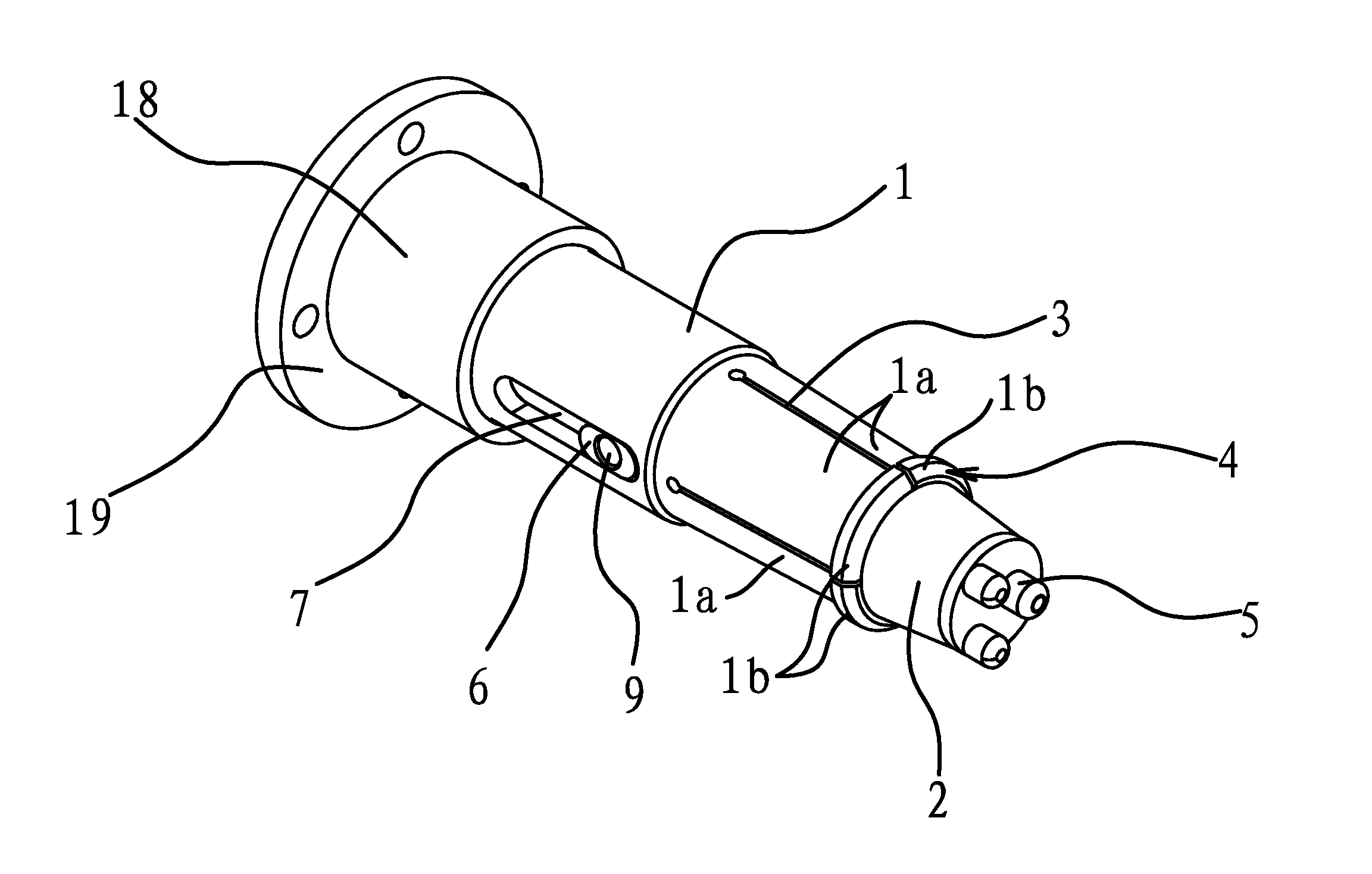
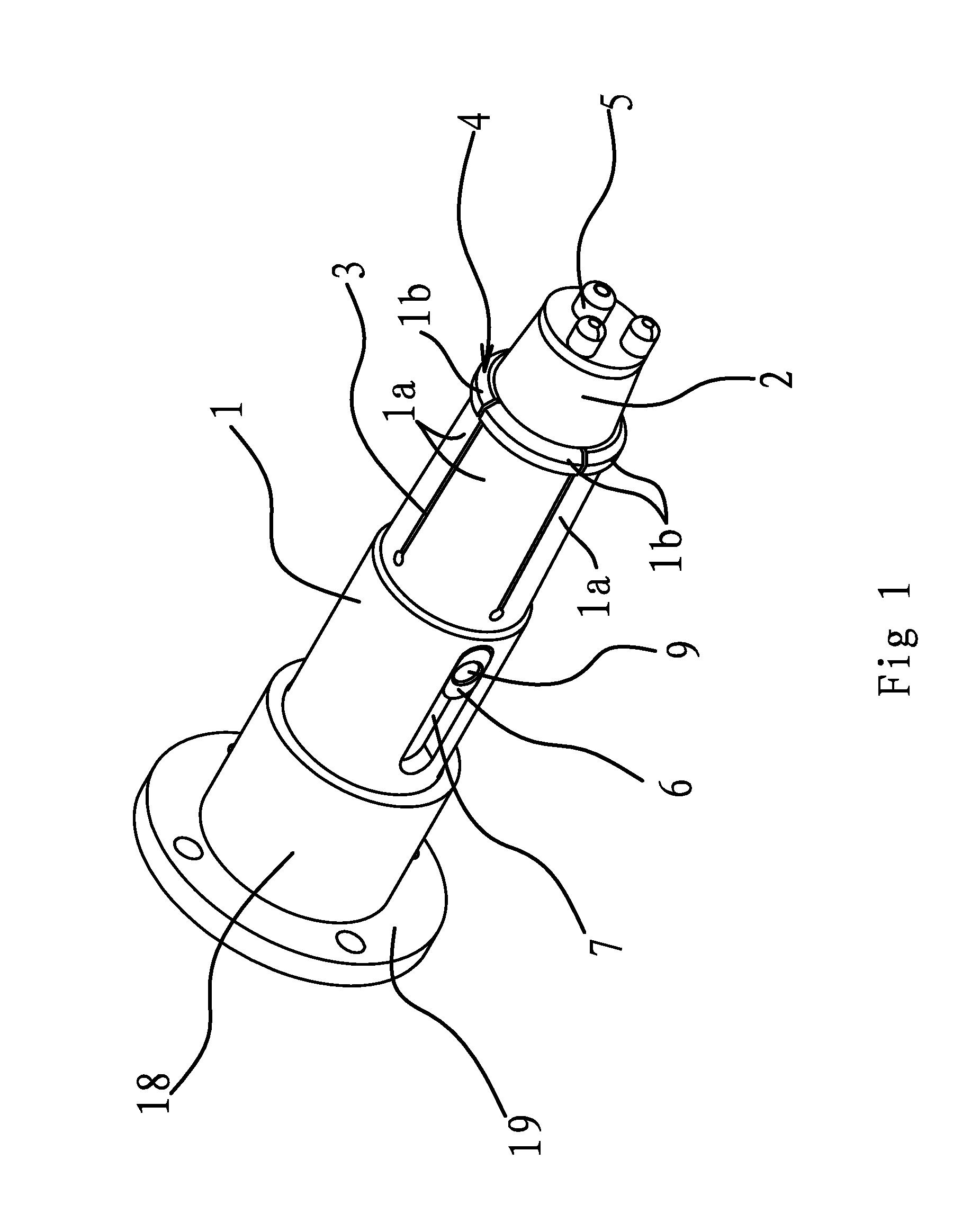
[0038]As shown in FIG. 1, the chuck is provided at the front end of the manipulator, comprising a chuck sleeve and an ejector pin 2 set within the chuck sleeve 1. An elastic clamping element 1a is provided at the front end of the chuck sleeve 1. The ejector pin 2 could move between a first position and a second position along the axial direction of the chuck sleeve 1. When the ejector pin 2 is in the first position, the outer circumference of the ejector pin 2 extrudes the clamping element 1a to distort and expand outward to form an expansion state. When the ejector pin 2 is in the second position, the outer circumference of the ejector pin 2 is out of contact with the clamping element 1a to restore the clamping element 1a. The ejector pin 2 is in the second position in use and the chuck sleeve 1 is in a normal status and inserted into the inner bore of the work piece such as a water faucet. When the ejector pin 2 is moved into the first position, the clamping element 1a is in the e...
second embodiment
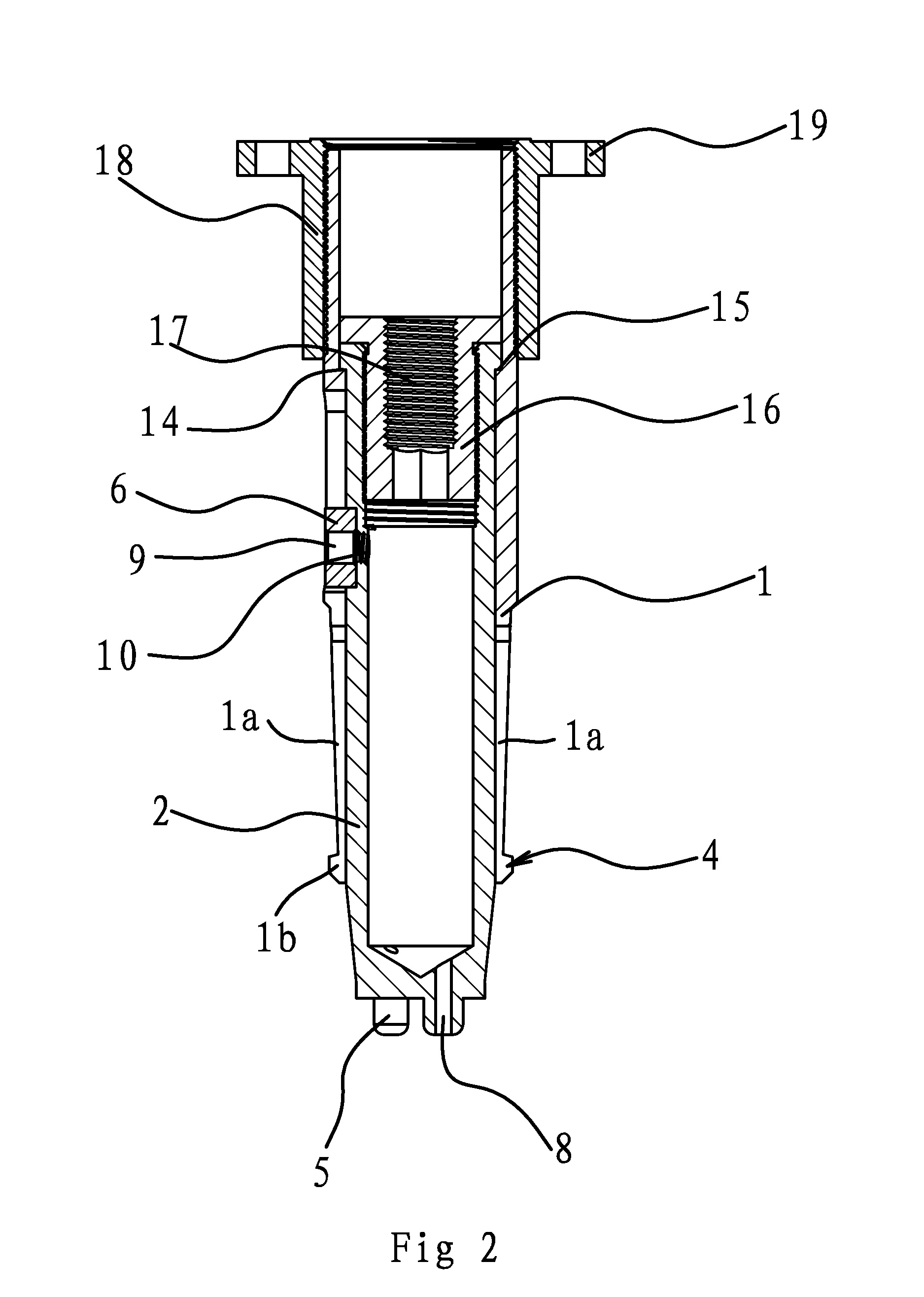
[0047]The structure and principle of this embodiment are substantially the same as those of the second embodiment except that, as shown in FIG. 3, two annular seal grooves 11 are opened on the side of the ejector pin 2 and an annular seal ring 12 is provided between the annular seal groove 11 and the inner side wall of the chuck sleeve 1. An annular groove 13 is further formed between two annular seal grooves 11 on the side of the ejector pin 2. The air exiting means includes an air hole 10 which is provided at the annular groove 13 and in communication with the inner cavity of the ejector pin 2 and an air inlet 9 which is disposed on the side of the chuck sleeve 1 and in communication with the air hole 10. The air inlet 9 is always located between two annular seal grooves 11 when the ejector pin 2 moves relative to the chuck sleeve 1 in the axial direction.
[0048]An air supply is connected with the air inlet 9 on the side of the chuck sleeve 1. While the ejector pin 2 is moved, the ...
PUM
 Abstract
Description
Claims
Application Information