Assembly connection flange and brake disc

a technology of connection flange and brake disc, which is applied in the direction of brake discs, mechanical devices, transportation and packaging, etc., can solve the problems of large increase, considerable heating of bearings and all the components contiguous thereto, and particularly limited friction between the axle and the hub, etc., and achieves the effect of simple implementation and easy maintenan

Active Publication Date: 2015-01-15
FRENI BREMBO SPA
View PDF7 Cites 19 Cited by
  • Summary
  • Abstract
  • Description
  • Claims
  • Application Information

AI Technical Summary

Benefits of technology

[0015]Therefore, it is the object of the present invention to devise a connection flange to a wheel rim and a flange and brake disc assembly that allows solving the drawbacks of the state of the art, while allowing a suitable cooling of the bearing and of the brake disc, as well as providing a solution simple to be implemented and easy in maintenance that prevent the direct connection of the brake disc to the wheel rim.
[0018]By virtue of the provision of an outer drum surface radially more outside with respect to the lower or radially inner edge of the flange opening, it is possible to bring part of the drum in communication with the opening of the cooling fluid evacuation flange, allowing the cooling of the bearing as well as the cooling of the brake disc.
[0019]Furthermore, by virtue of the provision of a drum for brake disc, on the edge of which an opening is foreseen for the evacuation of the cooling fluid from the gap inside the drum that separates it from the bearing outside the rim, passing through the flange opening, it is possible to suitably cool also the inside of the drum, and therefore directly also the bearing, bringing it in direct communication with the outside of the wheel rim.
[0020]Furthermore, by virtue of the described solutions, it is possible to disassemble the wheel without separating the flange from the rim, so as to make particularly easy and rapid the possible replacing of the worn disc.
[0021]Furthermore, in accordance with an embodiment, the number of the flange openings is equal to the number of the openings foreseen on the drum edge, reducing the total number of flange openings and making the latter much more resistant to the stresses that are present, for example, in the commercial vehicles. At the same time, the foreseen solution allows having a flange body, and particularly a disc coupling inner ring thereof, in a lighter weight, but at the same time sufficiently robust, since it is coupled with a large extension or connection portion thereof to the drum flange, thereby being a thin flange inner ring, yet suitably robust, while allowing a lightening of the assembly on the whole.
[0022]By virtue of the proposed solution, it is possible to free the brake disc from the wheel rim and interpose it between the flange and the bearing, while preserving a suitable ventilation of the bearing, allowing the evacuation of cooling fluid from the gap between the bearing and the disc directly outside the wheel.

Problems solved by technology

Although the friction between the axle and the hub is particularly limited, by virtue of the use, for example, of volving bearings, for example roll bearings, in the case that the action to be transmitted through the bearing is particularly high, a considerable heating of the bearing and of all the components contiguous thereto is created.
The fact that the disc for disc brake is connected to the support hub of the wheel rim, determines, in the case of repeated and intense braking actions, for example in the case that the vehicle has to go downhill of a mountain pass, a great increase in the temperature of the disc for disc brake and also of its portions connected to the hub, and in particular to the bearing, thus causing an even considerable heating of the bearing housed therein.
In the case that the brake disc is not suitably cooled, it is possible to compromise the proper operation not only of the disc, but also of the bearing.
This solution has considerable drawbacks, because it allows the passage of cooling air through openings of the hub and rim connection flange by evacuating the heat developed by the braking surfaces, particularly the braking surface facing the rim, but in no way it can concur to the cooling of the heat developed by the bearing, or transmitted to the bearing, through the drum from the brake disc.

Method used


Image

  • Assembly connection flange and brake disc
  • Assembly connection flange and brake disc
  • Assembly connection flange and brake disc

Examples


Embodiment Construction

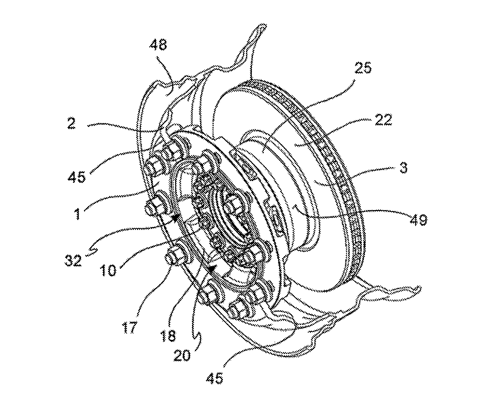
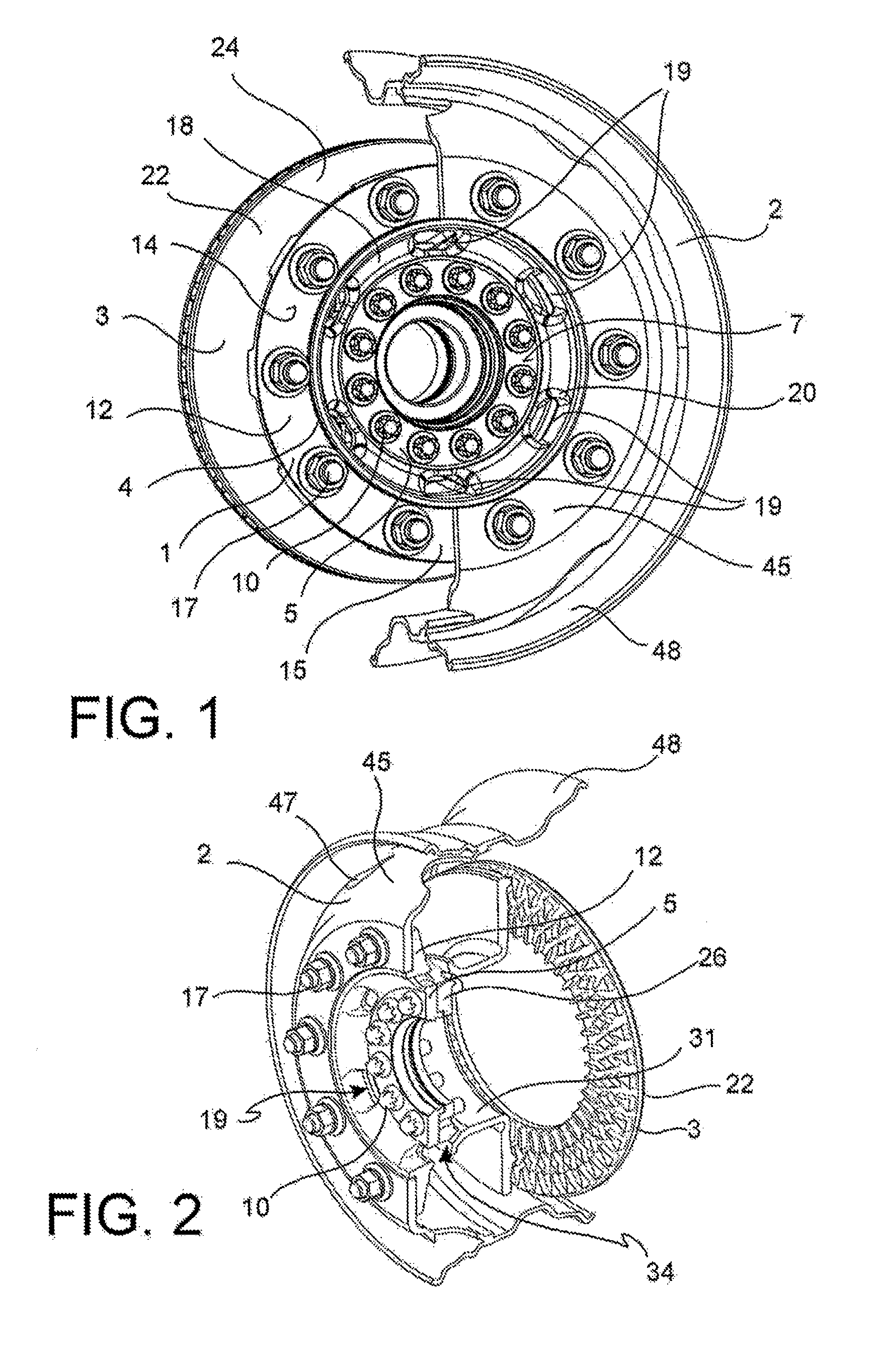
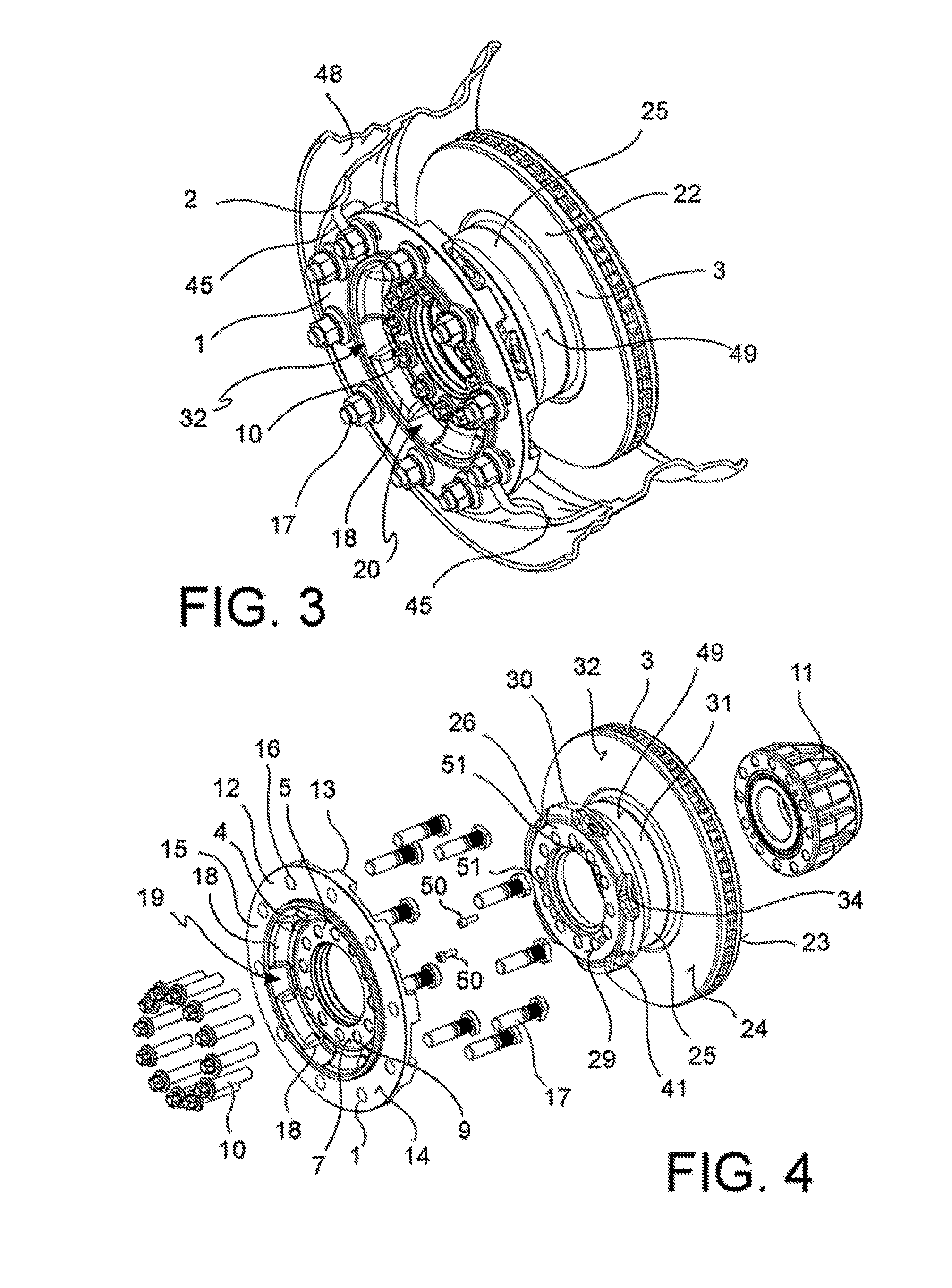
[0038]As it is possible to see from the annexed Figures, in accordance with a general embodiment, an assembly comprises a connection flange or flange 1 and a disc or disc for disc brake 3.

[0039]In accordance with an embodiment, the disc 3 has a brake band 22 suitable for cooperating with a caliper for disc brake to exert a braking action on a vehicle. Said disc 3 also comprises a drum 25. Said drum 25 has an outer drum surface 49. Said drum 25 is suitable for receiving a bearing 11 inside said drum, which is suitable to be shrunk on a shaft or an axle of the vehicle.

[0040]In accordance with a preferred embodiment, said disc 1 is interposed between the bearing 11 and the connection flange 1, and in accordance with an embodiment, said disc is able to be firmly connected to the bearing so as to allow separating the connection flange 1 without separating the disc from the bearing.

[0041]In accordance with an embodiment, the flange 1 comprises an inner ring 5. Said inner ring 5 is coupled...


PUM

PropertyMeasurementUnit
distanceaaaaaaaaaa
torqueaaaaaaaaaa
frictionaaaaaaaaaa

Abstract

An assembly comprises a flange and a disc, wherein the disc has a brake band and a drum, said drum having an outer drum surface, said drum being suitable for receiving a bearing inside said drum, said disc being arranged between the bearing and said flange, and wherein the flange comprises an inner ring coupled with the disc and an outer ring able to be coupled with a wheel rim, said flange also comprising an intermediate portion having flange through openings defined by an opening edge, said opening edge comprises a radially most inner edge portion, wherein at least one portion of the outer surface of the drum of the disc is arranged radially outside of the edge portion of the flange opening arranged most radially inside.

Description

BACKGROUND OF THE INVENTION[0001]1. Field of the Invention[0002]The present invention relates to an assembly of connection flange to a wheel rim and a brake disc.[0003]In particular, the present invention relates to an assembly of connection flange to a wheel rim and brake disc, for example for commercial vehicles.[0004]2. Description of the Prior Art[0005]As it is known, the commercial vehicles have support members of the wheel rims, or hubs, comprising bearings that are sufficiently robust to be able to support high transport loads.[0006]Typically, these hubs are connected to axles or traction axles, or motors, which allow a free rotation of the bearing, and therefore of the wheel rim connected thereto, or the transmission of a torque.[0007]In the case that these hubs are used for commercial vehicles, the housed bearings have to support even very high loads. Although the friction between the axle and the hub is particularly limited, by virtue of the use, for example, of volving be...

Claims


Application Information

Patent Timeline
Patent Type & Authority Applications(United States)
IPC IPC(8): F16D65/12B60B21/00
CPCB60B21/00F16D65/123F16D65/128Y10T29/49526F16D65/847F16D2065/1308F16D2065/1328F16D2065/1356F16D2065/1392B60B3/16B60B23/10B60B27/0052B60B27/0057
Inventor OBERTI, LEONEMARONATI, GIANLUIGIRONCHI, NINO
Owner FRENI BREMBO SPA
Why Eureka
Try Eureka