Electrical contactor

a contactor and electric technology, applied in the direction of contacts, coupling device connections, electromagnetic relay details, etc., can solve the problems of increasing manufacturing costs, increasing the number of blades and contacts, and causing a large amount of shock hazards, etc., to achieve the effect of improving the closure of the conta

Active Publication Date: 2015-01-15
JOHNSON ELECTRIC SA
View PDF10 Cites 13 Cited by
  • Summary
  • Abstract
  • Description
  • Claims
  • Application Information

AI Technical Summary

Benefits of technology

[0032]According to a third aspect, the present invention provides a method of improving contact closure through preventing or limiting rotational clamping, the method comprising the step of providing a distal extension element distally of a movable electrical contact on opposing movable arms of an electrical contactor, and a movable biasing element which moves into a biasing position against each distal extension element when the movable electrical contacts close with associated fixed electrical contacts of the electrical conta...

Problems solved by technology

A dangerous shock hazard can also occur if the Load, that is thought to be disconnected safely, is still live at mains voltage.
A problem associated with the higher current 200 Amp two-pole meter Load-disconnect contactor is the number of blades and...

Method used


Image

  • Electrical contactor
  • Electrical contactor
  • Electrical contactor

Examples


Embodiment Construction

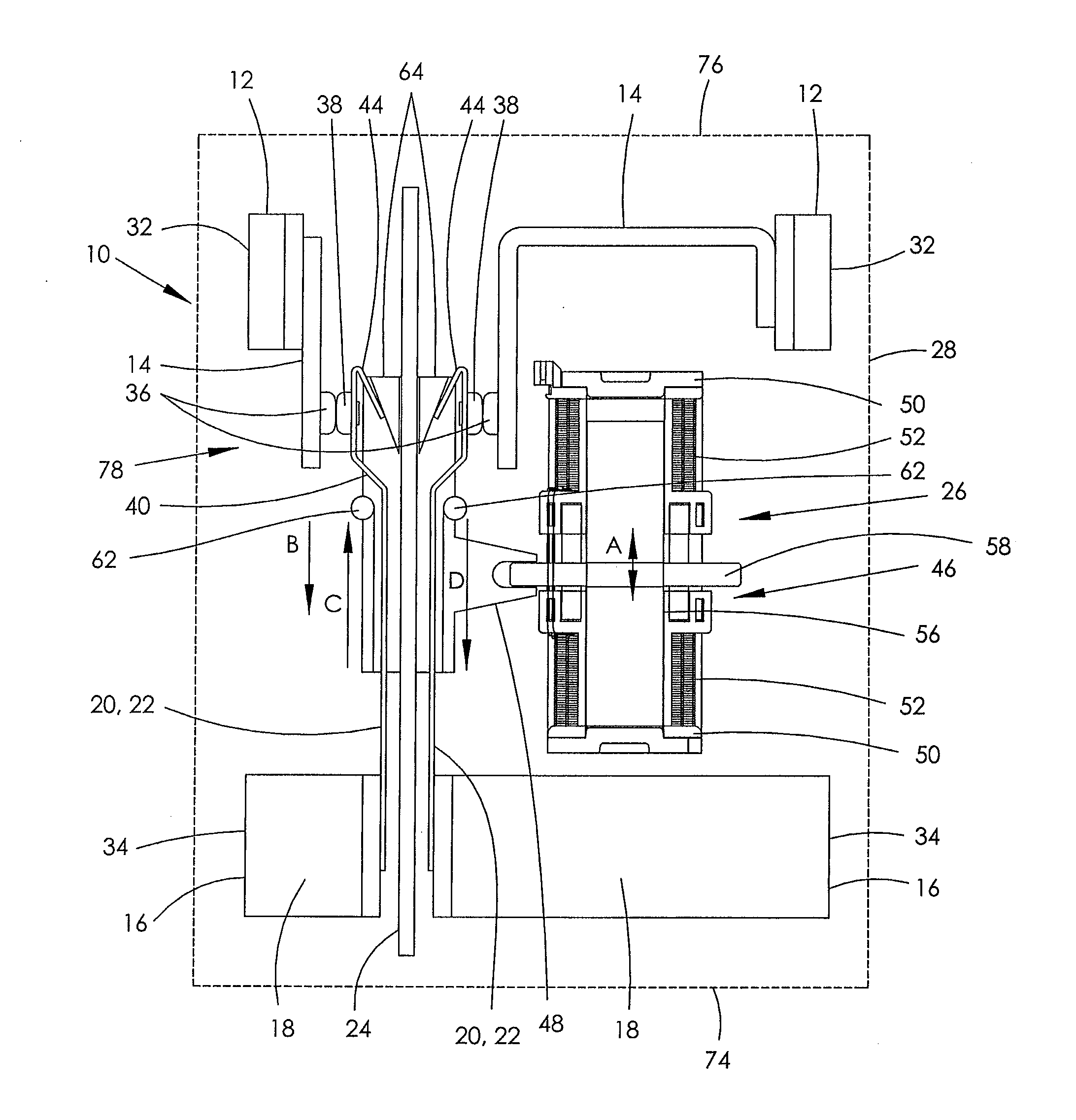
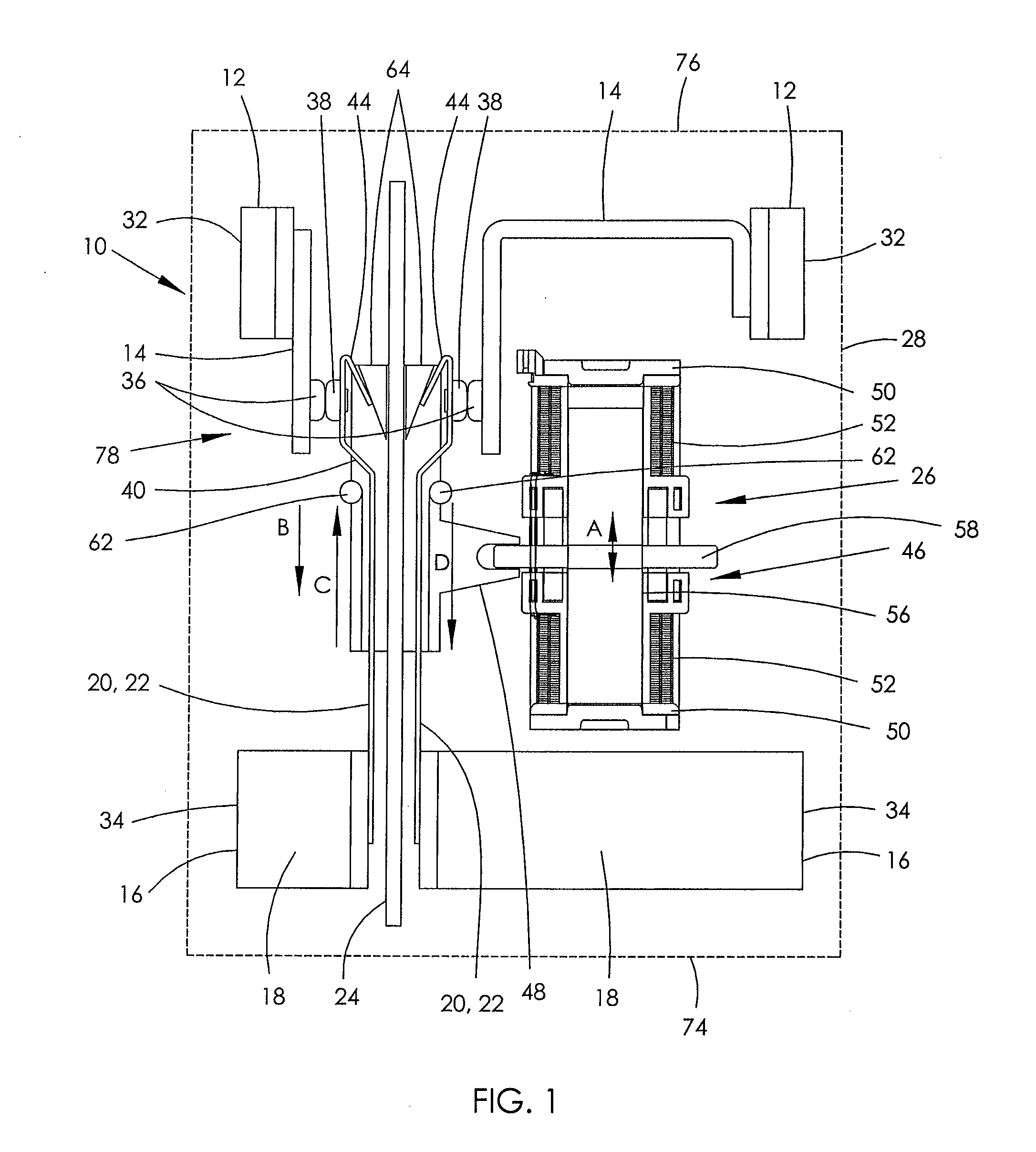
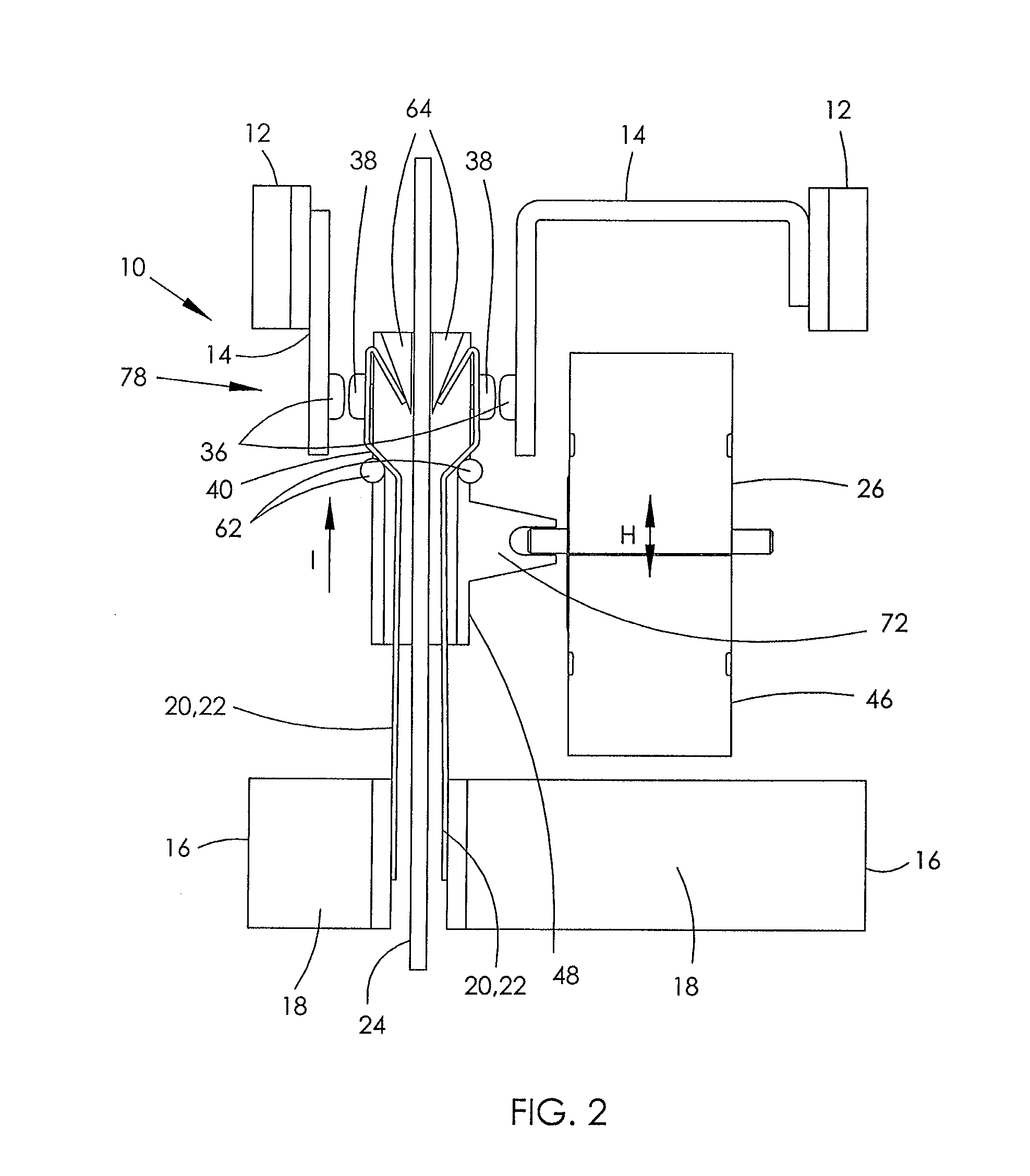
[0040]Referring firstly to FIGS. 1 to 4 of the drawings, there is shown a first embodiment of a two-pole electrical contactor 10 which comprises two first terminals 12 each having facing fixed members 14 of electrically conductive material, two second terminals 16 each having a terminal body 18 from which a plurality of back-to-back cantilever movable arms 20, 22 also of electrically-conductive material extend, an electrically-insulating partitioning element 24 interposed between the back-to-back movable arms 20, 22, and an actuator arrangement 26 for, in this embodiment, simultaneously moving the movable arms 20, 22 relative to the fixed members 14.

[0041]The first and second terminals 12, 16 are mounted to a base 28 of a housing, which in the drawings is shown with its cover removed. A first terminal pad 32 of each first terminal 12 and a second terminal pad 34 of each second terminal 16 extend from opposite ends of the housing base 28 in spaced apart relationship.

[0042]The electri...


PUM


Abstract

An electrical contactor has a pair of first terminals and a pair of second terminals. Each first terminal has a fixed member with at least one fixed electrical contact facing the other fixed member. The second terminals having back-to-back electrically-conductive movable arms with an electrically-insulating partitioning element there between. Each second terminal is associated with a different one of the first terminals, and has a movable electrical contact on the associated movable arm which faces the corresponding fixed contact. When the contacts close, contra-flowing current through the back-to-back movable arms produces a repulsive force between the movable arms increasing a force between the fixed and movable contacts.

Description

CROSS REFERENCE TO RELATED APPLICATIONS[0001]This non-provisional patent application claims priority under 35 U.S.C. §119(a) from Patent Application No. 1312463.1, filed in the United Kingdom on Jul. 11, 2013, the entire contents of which are hereby incorporated by reference.FIELD OF THE INVENTION[0002]The present invention relates to an electrical contactor, particularly but not necessarily exclusively for high-current switching contactors employed in modern electricity meters, so-called ‘smart meters’, for performing a load-disconnect function at normal domestic supply mains voltages, typically being 100 V AC to 250 V AC.[0003]The invention may also relate to an electrical contactor of a high current switch which may be subjected to a high short-circuit fault condition requiring the contacts to not weld.[0004]This invention therefore also relates to a two-pole electrical contactor, a single-phase electrical contactor for Live and Neutral feeds, a method of preventing or limiting e...

Claims


Application Information

Patent Timeline
IPC IPC(8): H01H3/00
CPCH01H3/001H01H1/54H01H50/56H01H50/641H01H50/54H01R12/71
Inventor CONNELL, RICHARD ANTHONY
Owner JOHNSON ELECTRIC SA
Why Eureka
Try Eureka