
Perceived Image Depth for Autostereoscopic Displays

a technology of autostereoscopic display and image depth, which is applied in the field of video autostereoscopic display, can solve the problems of increasing the number of optical aberrations and becoming problematic, and achieve the effect of reducing these optical aberrations and a more flat field of view

Inactive Publication Date: 2015-01-15
SOLIDDD
View PDF6 Cites 65 Cited by
  • Summary
  • Abstract
  • Description
  • Claims
  • Application Information

AI Technical Summary

Benefits of technology

The patent describes a way to make optical devices with less distortion. This is done by using special lenses called meniscus-cylinder lenses, which make the image look more complete. By using these lenses, researchers hope to create better quality optical devices with improved performance.

Problems solved by technology

One of the challenges with such long focal lengths in lenticles of a lenticular array is that a number of optical aberrations become noticeable and problematic.

Method used


Image

  • Perceived Image Depth for Autostereoscopic Displays
  • Perceived Image Depth for Autostereoscopic Displays
  • Perceived Image Depth for Autostereoscopic Displays

Examples


Embodiment Construction

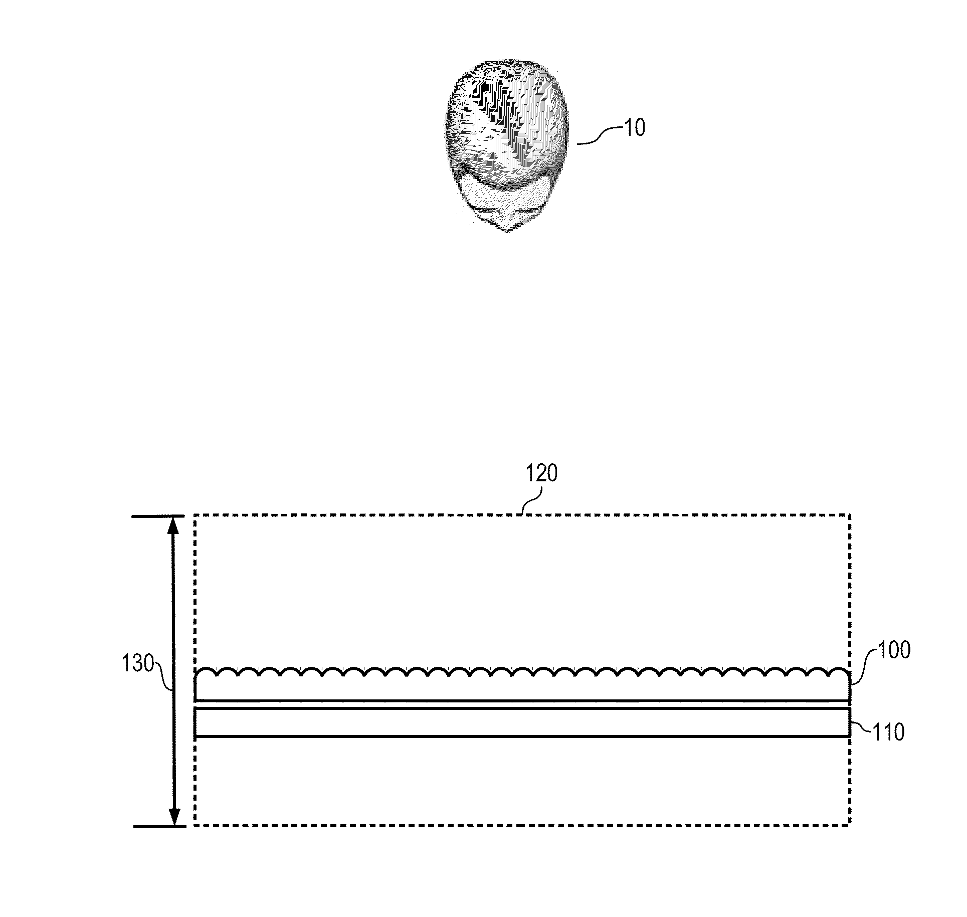
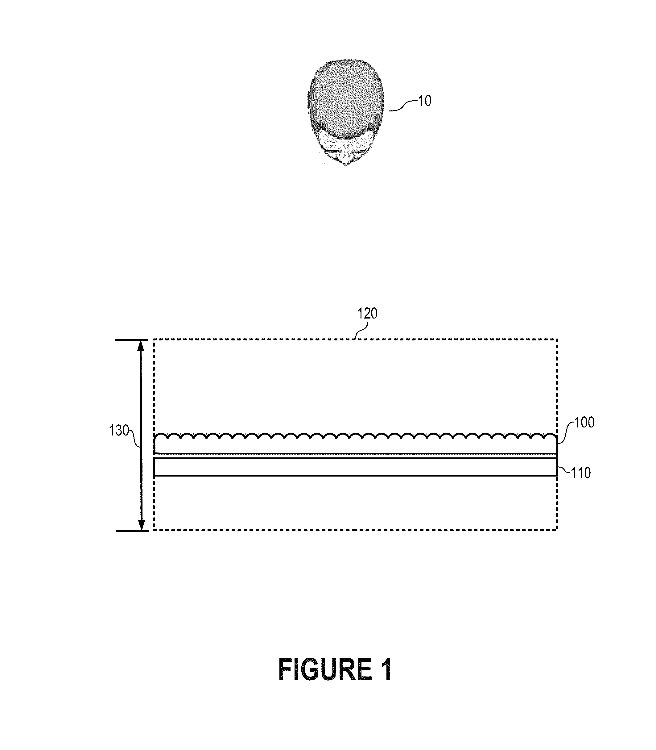
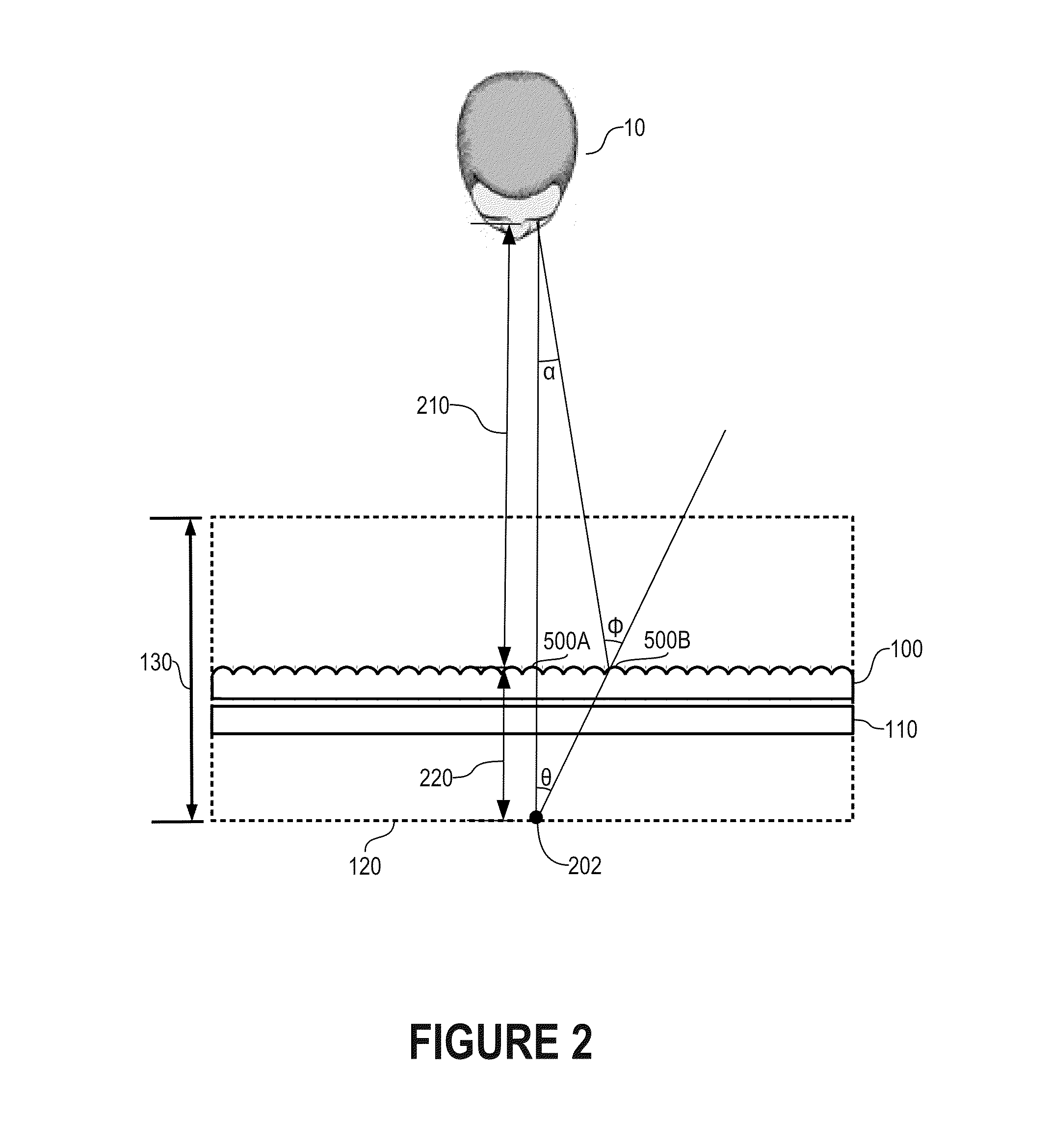
[0016]In accordance with the present invention, a depth 130 (FIG. 1) of a projection area 120 in which parts of an autostereoscopic display that includes a lenticular array 100 and a display 110 is dramatically improved—e.g., to a meter or more, 20-30 times what is seen in conventional autostereoscopic displays—by determining a relationship between depth 130 and an autostereoscopic display configuration at which a portion of display 110 can be visible at multiple locations (lenticular crosstalk). This relationship establishes a limiting configuration within which lenticular crosstalk is minimized. Once this relationship is determined for a desired depth 130, the autostereoscopic display is constructed to meet or exceed the autostereoscopic display configuration to ensure that lenticular crosstalk is only possible at depths of projection beyond depth 130.

[0017]The autostereoscopic includes a focal length of individual lenticles of lenticular array 100 and a number of views represente...


PUM


Abstract

An autostereoscopic display provides an extremely deep projection area by observing a relationship between a desired depth of projection and an autostereoscopic display design that includes a focal length of lenticles of a lenticular array and a number of views. The relationship specifies a projected depth at which lenticular crossover can occur for a given autostereoscopic with the specific lenticular focal length and number of views. Approximations can be used to simplify the relationship such that the projected depth is directly related to a product of the focal length and the number of views. To reduce optical aberrations, lenticles of the lenticular array include meniscus-cylinder lenses.

Description

FIELD OF THE INVENTION[0001]The present invention relates generally to autostereoscopic displays, and, more particularly, to a video autostereoscopic display with significantly improved depth of projection.BACKGROUND OF THE INVENTION[0002]Conventional autostereoscopic displays use arrays of lenses or parallax barriers or other view selectors to make a number of pixels of the display visible to one eye of a viewing person and to make a number of other pixels of the display visible to the other eye of the viewing person. By isolating the pixels of the display visible to each eye, the two fields of a stereoscopic image can be presented on the display. The presentation of separate fields to each eye is often used to cause the viewer to perceive a three-dimensional image.[0003]Current stereoscopic displays project a perceived depth of about a few centimeters. In other words, most autostereoscopic displays project portions of an image no more than about 1-2 centimeters in front of, and no...

Claims


Application Information

Patent Timeline
Patent Type & Authority Applications(United States)
IPC IPC(8): G02B27/22G02B30/27
CPCG02B27/2214G02B27/0075G02B30/27G02B30/29
Inventor MULLER, RICHARD A.
Owner SOLIDDD
Learn More