Systems and methods for integration of a positron emission tomography (PET) detector with a computed-tomography (CT) gantry

a computed tomography and detector technology, applied in tomography, applications, instruments, etc., can solve the problems of increasing the footprint of the system, increasing the size of the ct detector, and needing a larger imaging room

Active Publication Date: 2015-01-15
GENERAL ELECTRIC CO
View PDF4 Cites 17 Cited by
  • Summary
  • Abstract
  • Description
  • Claims
  • Application Information

AI Technical Summary

Problems solved by technology

However, having two imaging detector gantries (in tandem) increases the footprint of the system and consequently a larger imaging room is needed.
Further, newer CT detectors have an increasingly higher field of view, which increase the CT detector size.
The larger CT detector in these dual-modality CT / PET systems results in the PET detector being displaced further along into the bore volume.
Thus, the patient travels further into the bore volume, which can cause claustrophobia and general discomfort for certain patients.
However, it is not always desirable to rotate the PET ring.
However, this arrangement increases the difficulty of co-registration and alignment.

Method used


Image

  • Systems and methods for integration of a positron emission tomography (PET) detector with a computed-tomography (CT) gantry
  • Systems and methods for integration of a positron emission tomography (PET) detector with a computed-tomography (CT) gantry
  • Systems and methods for integration of a positron emission tomography (PET) detector with a computed-tomography (CT) gantry

Examples


Embodiment Construction

[0014]The following detailed description of certain embodiments will be better understood when read in conjunction with the appended drawings.

[0015]Furthermore, references to “one embodiment” are not intended to be interpreted as excluding the existence of additional embodiments that also incorporate the described features. Moreover, unless explicitly stated to the contrary, embodiments “comprising” or “having” an element or a plurality of elements having a particular property may include additional such elements not having that property. Furthermore, references to “one embodiment” are not intended to be interpreted as excluding the existence of additional embodiments that also incorporate the recited features. Moreover, unless explicitly stated to the contrary, embodiments “comprising” or “having” an element or a plurality of elements having a particular property may include additional such elements not having that property.

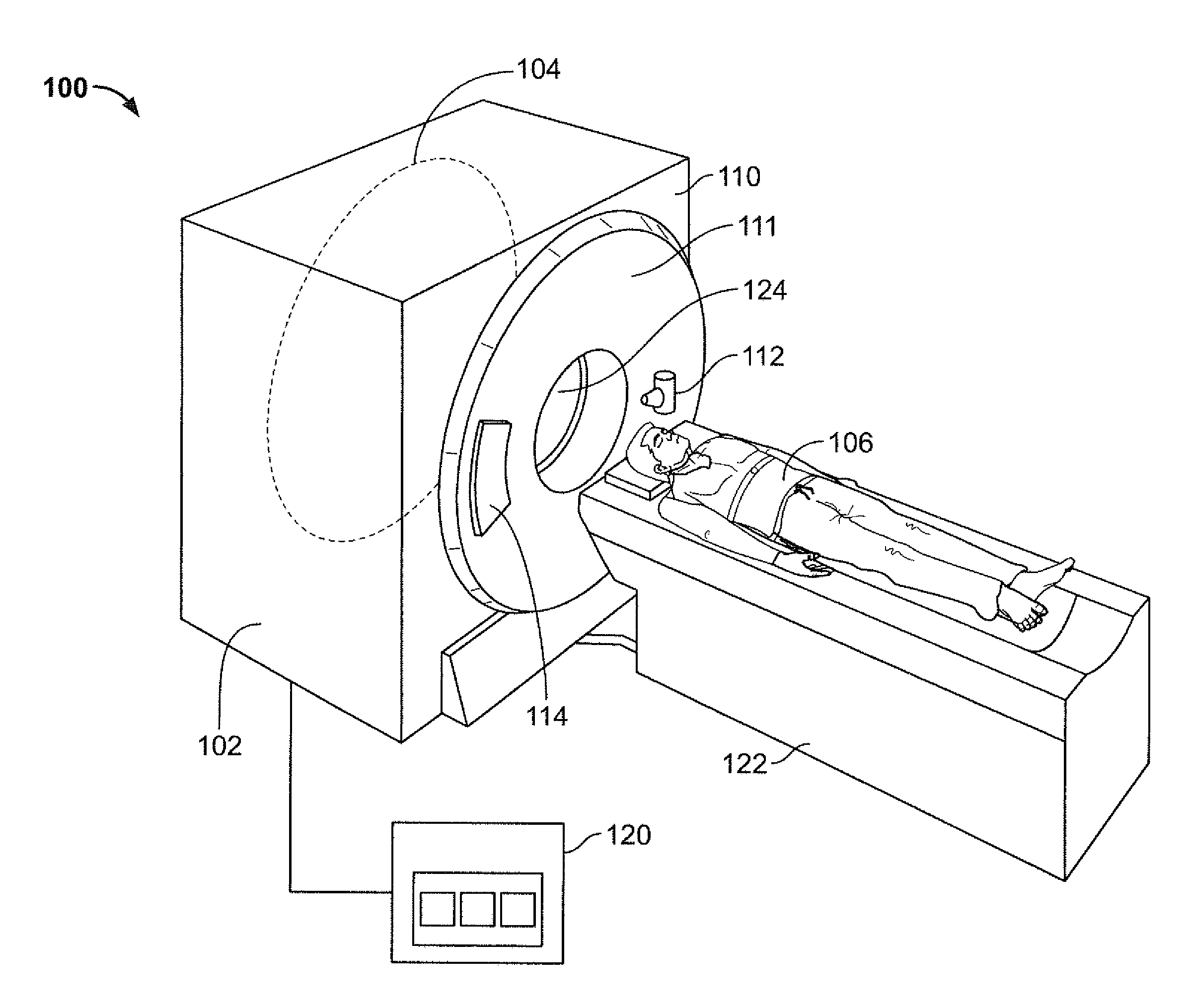
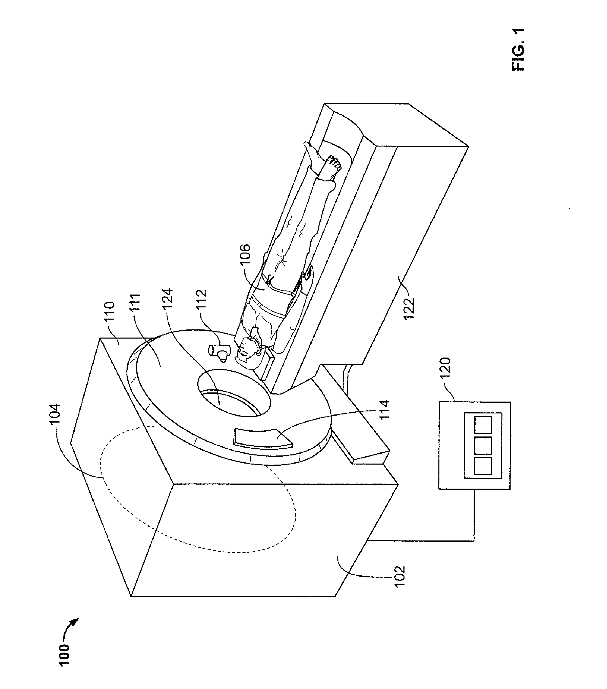
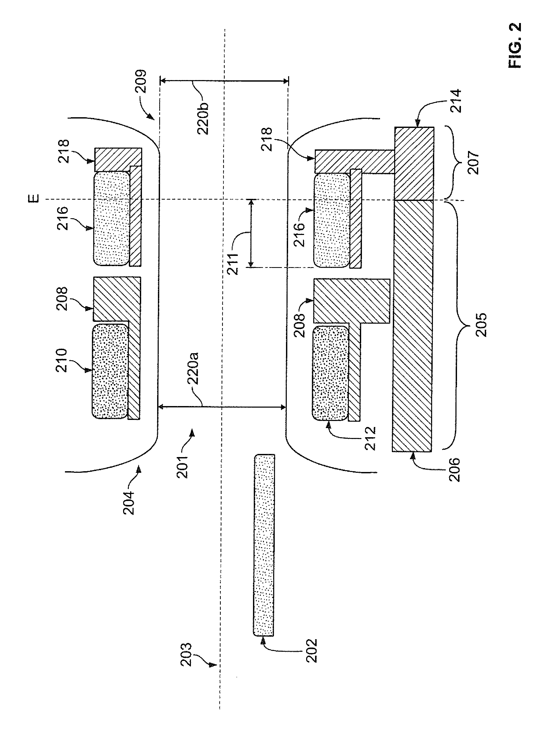
[0016]Various embodiments provide imaging systems that emp...


PUM


Abstract

Systems and methods for integration of a PET detector with a CT gantry are provided. One system includes an x-ray computed tomography (CT) gantry having a rotating portion and a stationary portion within a housing, and including a bore volume therethrough. The system also includes an x-ray source and an x-ray detector coupled to the rotating portion. The system further includes a positron emission tomography (PET) detector, wherein the PET detector is coupled to the stationary portion of the CT gantry, such that the PET detector extends at least partially into the CT gantry with at least a portion of the PET detector within the housing of the CT gantry.

Description

BACKGROUND OF THE INVENTION[0001]Embodiments described herein generally relate to imaging systems, particularly to multi-modality imaging systems, such as positron emission tomography (PET) / computed tomography (CT) systems.[0002]CT imaging systems typically include an x-ray source and a detector. In operation, the x-ray source and the detector are rotated around the object to be imaged such that an angle at which an x-ray beam intersects the object changes. A group of x-ray attenuation measurements, or projection data, from a detector at one gantry angle may be referred to as a “view.” A set of views made at different gantry angles during one revolution of the x-ray source and detector may be referred to as a “scan.” In an axial scan, projection data is processed to construct an image that corresponds to a two-dimensional cross-section or slice of an object being scanned.[0003]PET imaging systems may scan objects to acquire image information using non-moving detectors. During operat...

Claims


Application Information

Patent Timeline
Patent Type & Authority Applications(United States)
IPC IPC(8): A61B5/00A61B6/03
CPCA61B6/035A61B5/0035A61B6/032A61B6/037A61B6/4258A61B6/5247G01T1/2985
Inventor ROSE, TIMOTHY PATRICKMAKI, MICHAEL D.SMITH, CHAD ALLAN
Owner GENERAL ELECTRIC CO
Why Eureka
Try Eureka