Wearer Comfort Backpack Vacuum

Inactive Publication Date: 2015-01-22
TACONY A MISSOURI
View PDF11 Cites 18 Cited by
  • Summary
  • Abstract
  • Description
  • Claims
  • Application Information

AI Technical Summary

Benefits of technology

[0015]A secondary feature of the invention concerns the vacuum nozzle or other tool that is customarily attached to the outer most extent of the vacuum hose and which is used to contact the surface to be cleaned. Adjustment of the movable plate with

Problems solved by technology

However, one feature that has not, to Applicant's knowledge, been addressed in the prior art is that fact that backpack vacuum units tend to heat up the back region of the wearer in use.
While the various known harness de

Method used


Image

  • Wearer Comfort Backpack Vacuum
  • Wearer Comfort Backpack Vacuum
  • Wearer Comfort Backpack Vacuum

Examples


Example

[0020]The preferred version of the invention presented in the following written description and the various features and advantageous details thereof are explained more fully with reference to the non-limiting examples and as detailed in the description which follows. Descriptions of well-known components and processes and manufacturing techniques are omitted so as to not unnecessarily obscure the principle features of the invention as described herein. The examples used in the description which follows are intended merely to facilitate an understanding of ways in which the invention may be practiced and to further enable those skilled in the art to practice the invention. Accordingly, the examples should not be construed as limiting the scope of the claimed invention.

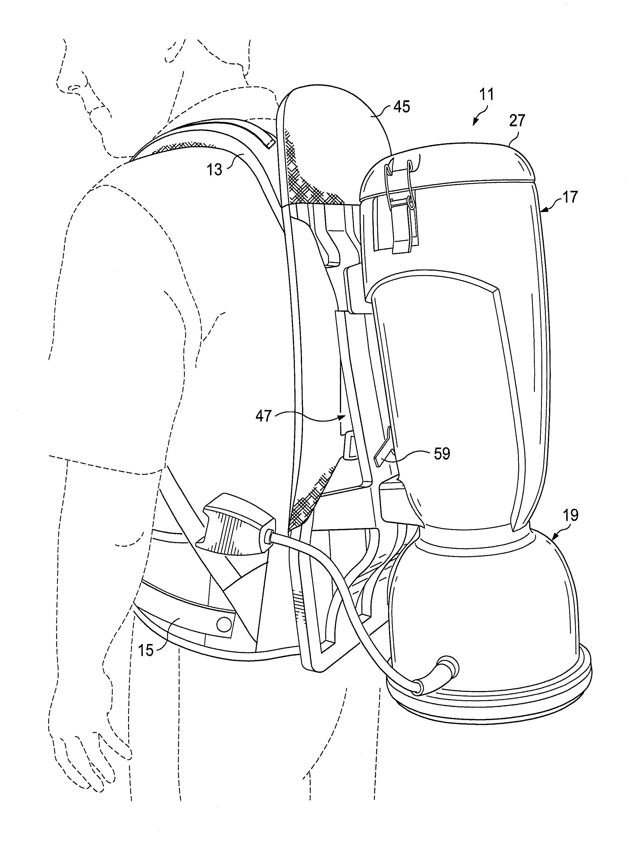
[0021]FIG. 1 is a perspective view of the wearer comfort backpack vacuum of the invention, designated generally as 11. The overall configuration of the backpack vacuum 11 is similar to that of several commercially avai...


PUM


Abstract

A backpack vacuum has a body made up of an upper cannister and a lower motor compartment. The vacuum body is supported on a wearer's back by a harness. A vacuum motor draws air from an opening in the upper cannister through a primary air flow path out an exhaust outlet from the lower motor compartment. An adjustable air flow opening in the cannister sidewalls creates a secondary air flow path through the vacuum body which creates a cooling air region adjacent the wearer's back in use.

Description

BACKGROUND OF THE INVENTION[0001]1. Field of the Invention[0002]The present invention relates generally to a portable vacuum system and, more specifically, to a backpack mounted portable vacuum system.[0003]2. Description of the Prior Art[0004]Portable vacuum systems, including backpack mounted vacuum systems, are known in the prior art. For example, Tacony, Inc., the assignee of the present invention presently markets a line of backpack vacuums under the Powr-Flite® brand, i.e., the PF600BP and PF1000BP models.[0005]Backpack mounted vacuum systems are also discussed in the patent art. For example, U.S. Pat. No. 5,267,371, to Soler et al., shows an early cyclonic back-pack vacuum cleaner featuring a wearer harness and associated upper and lower casing attached to the harness. A cyclonic cleaning assembly is contained within the upper casing.[0006]U.S. Pat. No. 5,588,177, to Eriksen, shows another backpack vacuum cleaner having a housing with a compartment for a filter bag, a connect...

Claims


Application Information

Patent Timeline
IPC IPC(8): A47L9/12A47L5/36
CPCA47L9/12A47L5/36A47L9/22A47L5/365A47L9/2889A47L5/24
Inventor DAY, ALAN, STEVEN
Owner TACONY A MISSOURI
Why Eureka
Try Eureka