Test station for portable gas measuring devices

Active Publication Date: 2015-01-22
DRAGER SAFETY
View PDF0 Cites 6 Cited by
  • Summary
  • Abstract
  • Description
  • Claims
  • Application Information

AI Technical Summary

Benefits of technology

The present invention improves a test station for portable gas measuring devices by allowing multiple devices to be tested in parallel, reducing testing time and minimizing test gas usage. The testing process is initiated by the carrier of the device, allowing for decentralized testing and reducing the main unit's reliance on the carrier. The invention also enables faster processing of multiple devices simultaneously, effectively using test gases in a more efficient manner.

Problems solved by technology

In everyday operation, however, the situation frequently arises that a plurality of operators insert their gas measuring device into a test module chronologically one after the other and then want to have a test result as soon as possible.

Method used


Image

  • Test station for portable gas measuring devices
  • Test station for portable gas measuring devices
  • Test station for portable gas measuring devices

Examples


Embodiment Construction

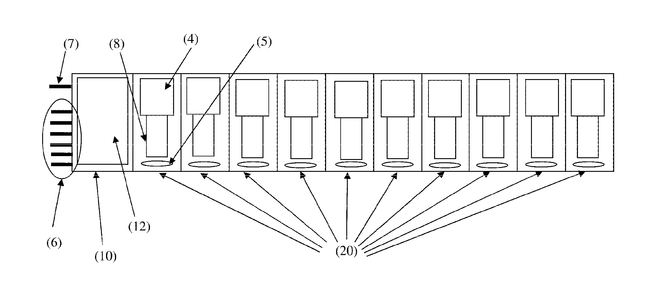
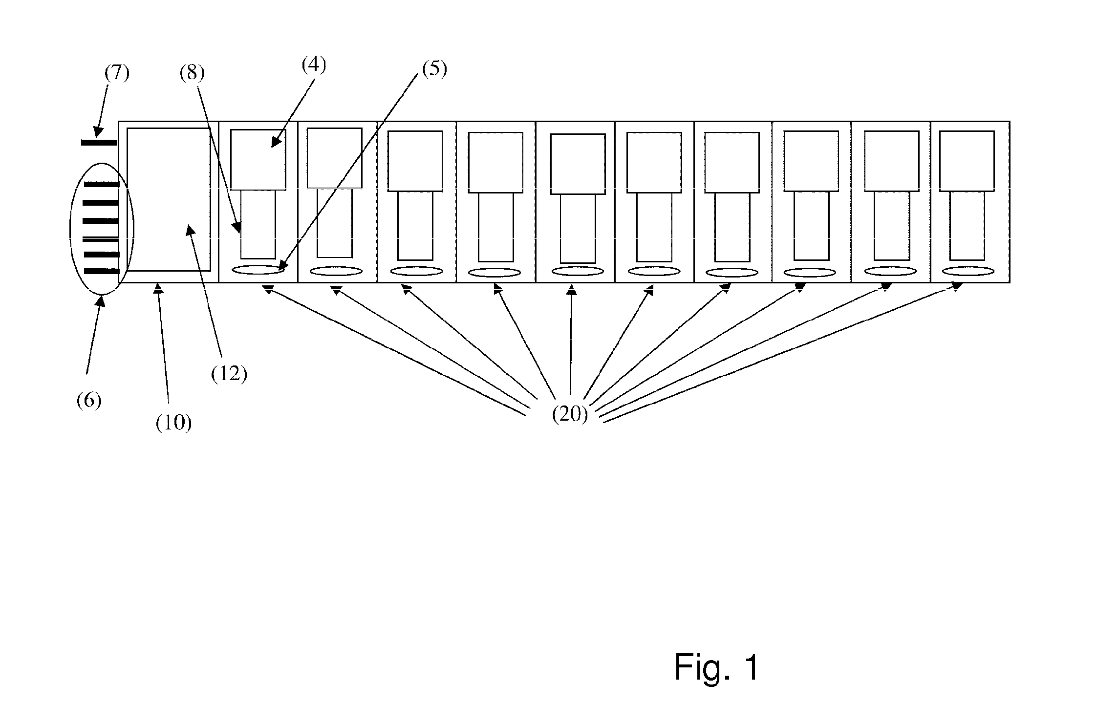
[0023]Referring to the drawings in particular, the test station schematically shown in FIG. 1 comprises a main unit 10 and ten test modules 20 in this exemplary embodiment. The main unit 10 is connected to the test modules 20 by means of a bidirectional data link for the purpose of exchanging data. Further, a common gas line leads out of the main unit 10 to the test modules; the test modules 20 are connected in parallel to the gas line and are each provided with valve means, which, controlled by the main unit 10, open or close the flow of test gas from the gas line to the individual test module.

[0024]In the exemplary embodiment shown, six gas inlets 6 for different test gases are provided at the main unit 10. After selecting one of the gas inlets 6, the common gas line is supplied with the selected test gas. The test gas is again discharged to the outside by means of the waste gas line 7.

[0025]When a gas measuring device 8 is inserted into one of the test modules 20 and the flap 4 i...


PUM


Abstract

A test station for a plurality of test gases, includes a main unit (10) with a control (12) and test modules (20), each for a gas measurement device, that exchange data to register a type of gas measurement device and test gas(es) required for the device type. The control sets a schedule for a test using a test gas, or for a plurality of successive tests each with different test gases and carries out the specific test planned according to the schedule, in parallel with tests for all of the test modules for a test gas and determines, as an additional gas measurement device is inserted, based on the particular device type of the additional gas measurement device, whether the currently-running test with the current test gas is suitable for the inserted test module; and if the test gas is suitable, to start the test for this test module.

Description

CROSS REFERENCE TO RELATED APPLICATIONS[0001]This application is a United States National Phase Application of International Application PCT / EP2013 / 061916 filed Jun. 10, 2013 and claims the benefit of priority under 35 U.S.C. §119 of German Patent Application DE 10 2012 210 090.3 filed Jun. 15, 2012, the entire contents of which are incorporated herein by reference.FIELD OF THE INVENTION[0002]The present invention pertains to a test station for portable gas measuring devices for a plurality of test gases, comprising a main unit including a control and analysis unit, and comprising a plurality of test modules connected to the main unit for the purpose of exchanging data, into each of which a gas measuring device can be inserted for testing, whereby means are provided for detecting the type of the respective gas measuring device that has been inserted into a test module and for determining the test gas or test gases required for this type of device, and whereby the main unit comprises...

Claims


Application Information

Patent Timeline
IPC IPC(8): G01N33/00
CPCG01N33/0004G01N33/0006G01N33/007
Inventor OSTERMANN, ULFKANEBLEI, INGOBARTEN, STEFANMOLLER, CHRISTOFSCHIMMEL, SVEN
Owner DRAGER SAFETY
Why Eureka
Try Eureka