Servo Flow Recirculation for an Advanced Thermal Efficient Aircraft Engine Fuel System

a fuel system and fuel flow technology, applied in water supply installation, machines/engines, positive displacement liquid engines, etc., can solve the problems of increasing system pressure at relight, and achieve the effect of facilitating the implementation of this invention, increasing system pressure, and high relight pressur

Active Publication Date: 2015-01-22
WOODWARD GOVERNOR CO
View PDF11 Cites 4 Cited by
  • Summary
  • Abstract
  • Description
  • Claims
  • Application Information

AI Technical Summary

Benefits of technology

[0008]The implementation of this invention is facilitated by recent combustor designs that lead to high relight pressures. Advanced combustion systems tend to lead to increased system pressure at relight and throughout the engine operating range. The relatively high relight pressure and operating pressures allow multiple servos to be run in series without requiring the supply pump differential pressure to be actively increased to support the pressure requirements of the servos.

Problems solved by technology

Advanced combustion systems tend to lead to increased system pressure at relight and throughout the engine operating range.

Method used


Image

  • Servo Flow Recirculation for an Advanced Thermal Efficient Aircraft Engine Fuel System
  • Servo Flow Recirculation for an Advanced Thermal Efficient Aircraft Engine Fuel System
  • Servo Flow Recirculation for an Advanced Thermal Efficient Aircraft Engine Fuel System

Examples


Embodiment Construction

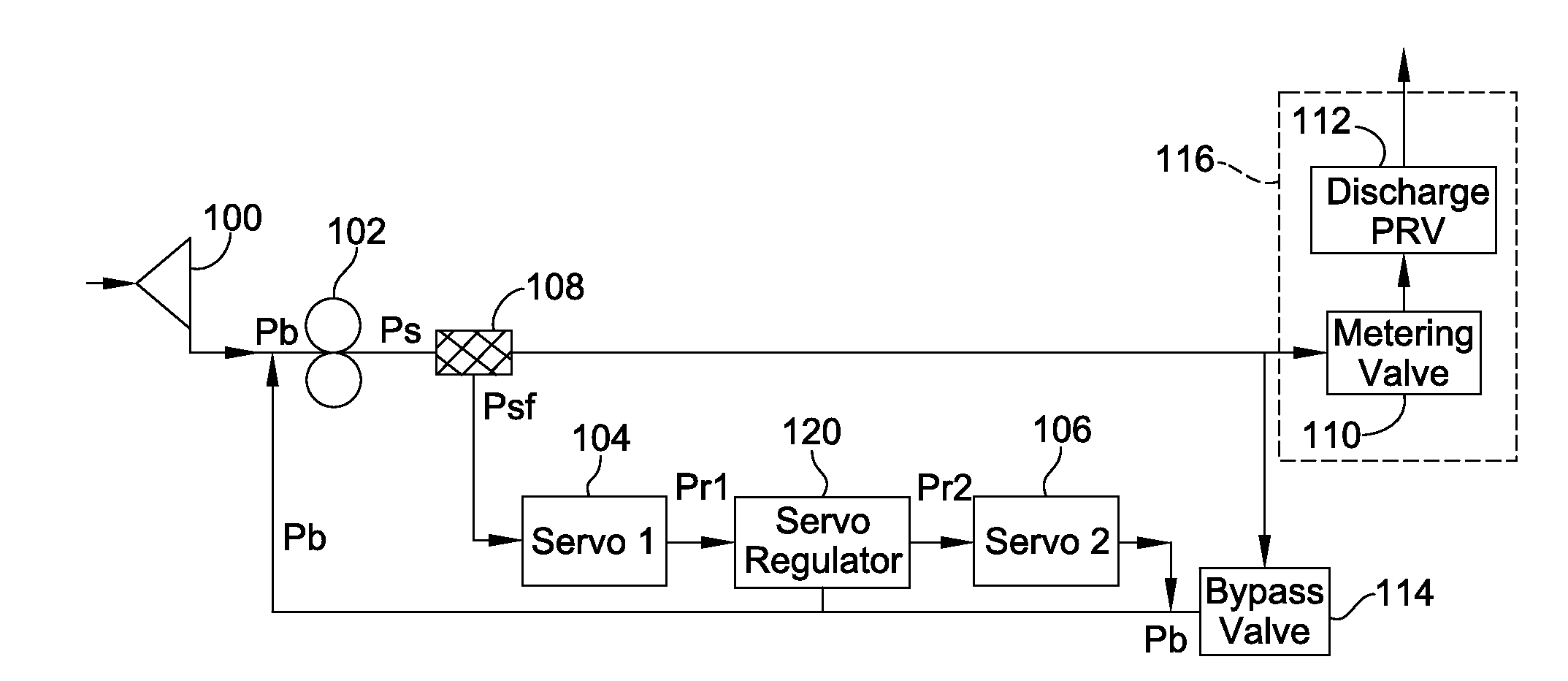
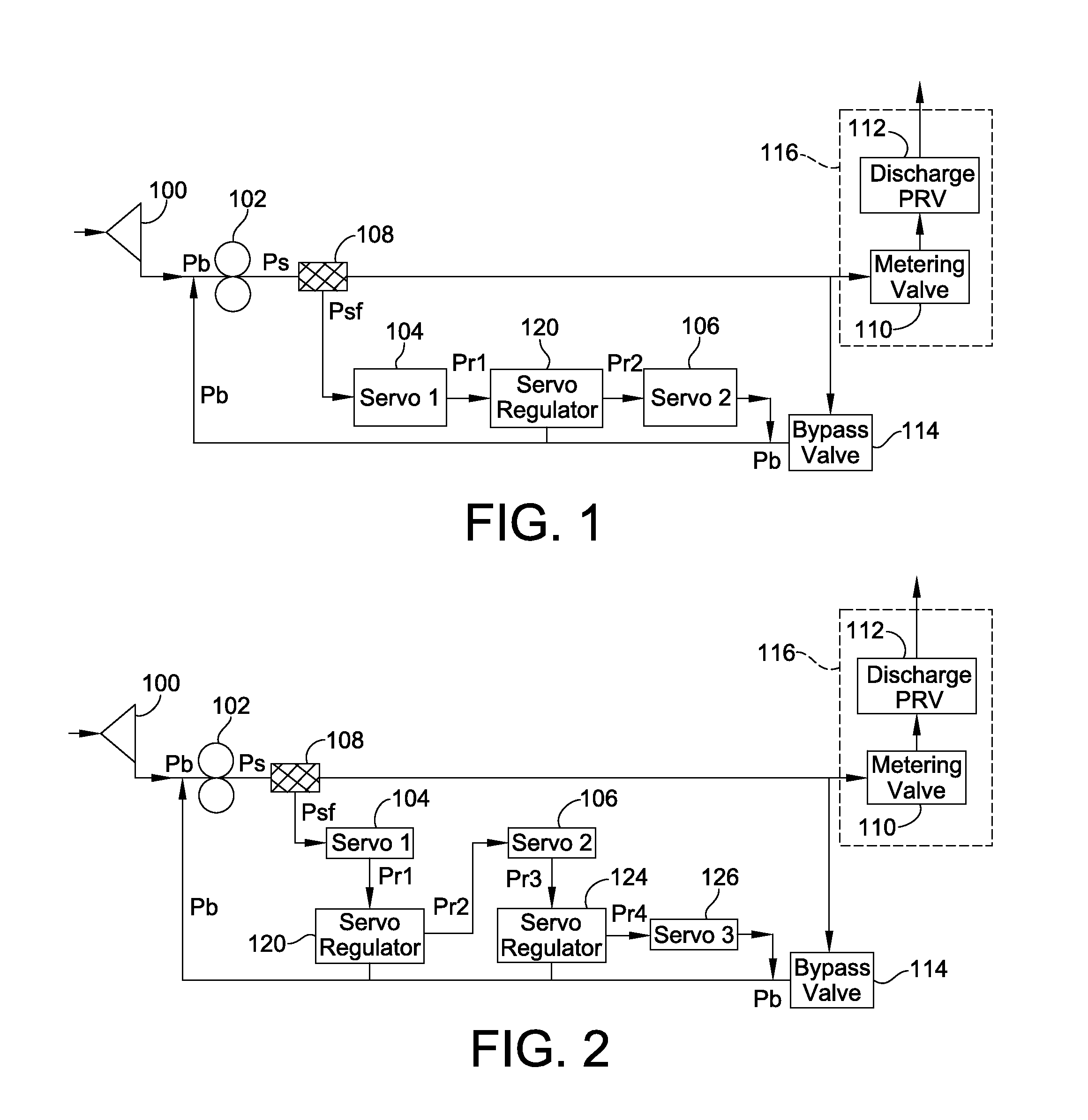
[0032]Turning now to the drawings, particularly FIG. 1, the same shows one implementation of servo flow recirculation shown in a simplified fuel system. In this embodiment, a boost pump 100 is connected in series to a supply pump 102. A control arrangement which includes first and second servos 104, 106 as well as a servo regulator 120 is operably connected to an outlet of supply pump 102. First and second servos 104, 106 are connected in series to one another. In the illustrated embodiment, servo regulator 120 is interposed between servos 104, 106 and may take the form of a pressure regulation device or a combined flow and pressure regulation device. The term “servo” as used herein denotes an individual servo as well as a grouping of servos. Indeed, either of servos 104, 106 may be indicative of a plurality of servos of a fuel circulation system, and can thus each be generally considered as a servo grouping which may include one or more individual servo devices.

[0033]Supply pump 10...


PUM


Abstract

A fuel circulation system and methods are provided. The system includes a supply pump for providing an outlet flow of fuel. The system also includes at least a first and a second servo. The first servo is connected to an outlet of the supply pump. A flow regulation device is interposed between the first and second servos. At least a portion of the outlet flow from the supply pump is directed through the first servo, flow regulation device, and second servo and is returned to an inlet of the supply pump.

Description

FIELD OF THE INVENTION[0001]This invention generally relates to aircraft fuel circulation systems, and more particularly to fuel flow recirculation of one or more electro-hydraulic servo valves of a fuel system.BACKGROUND OF THE INVENTION[0002]A typical aircraft engine fuel system includes a fuel supply arrangement that includes a boost pump, and a supply pump. The supply arrangement provides an outlet flow of fuel that may be used in one or more metering circuits each of which are responsible for metering fuel in a combustion engine, and / or an outlet flow of fuel that may be used for other functions, e.g. actuator control. In the context of metering circuits, the metering of fuel in each metering circuit is achieved via a fuel metering valve (FMV). The control of the fuel metering valve is achieved via an electro-hydraulic servo valve (EHSV). In the context of actuator control, actuator positions are controlled via an EHSV.[0003]Each EHSV receives an input supply of fuel which is u...

Claims


Application Information

Patent Timeline
Patent Type & Authority Applications(United States)
IPC IPC(8): F02M37/00F02M37/04
CPCF02M37/0023F02M37/0052F02M37/04F02M37/0047Y10T137/0318Y10T137/85986F05D2270/092F02C7/236F02C9/263F05D2260/606Y10T137/87917F02C7/232F05D2270/64F02C7/22
Inventor BAKER, CARTHEL, C.
Owner WOODWARD GOVERNOR CO
Why Eureka
Try Eureka