Rotor hub of a wind turbine generator system

Inactive Publication Date: 2015-01-22
SIEMENS AG
View PDF4 Cites 7 Cited by
  • Summary
  • Abstract
  • Description
  • Claims
  • Application Information

AI Technical Summary

Benefits of technology

[0009]An aspect relates to an assembly comprising a rotor hub and

Problems solved by technology

Work of this kind entails a hi

Method used


Image

  • Rotor hub of a wind turbine generator system
  • Rotor hub of a wind turbine generator system
  • Rotor hub of a wind turbine generator system

Examples


Embodiment Construction

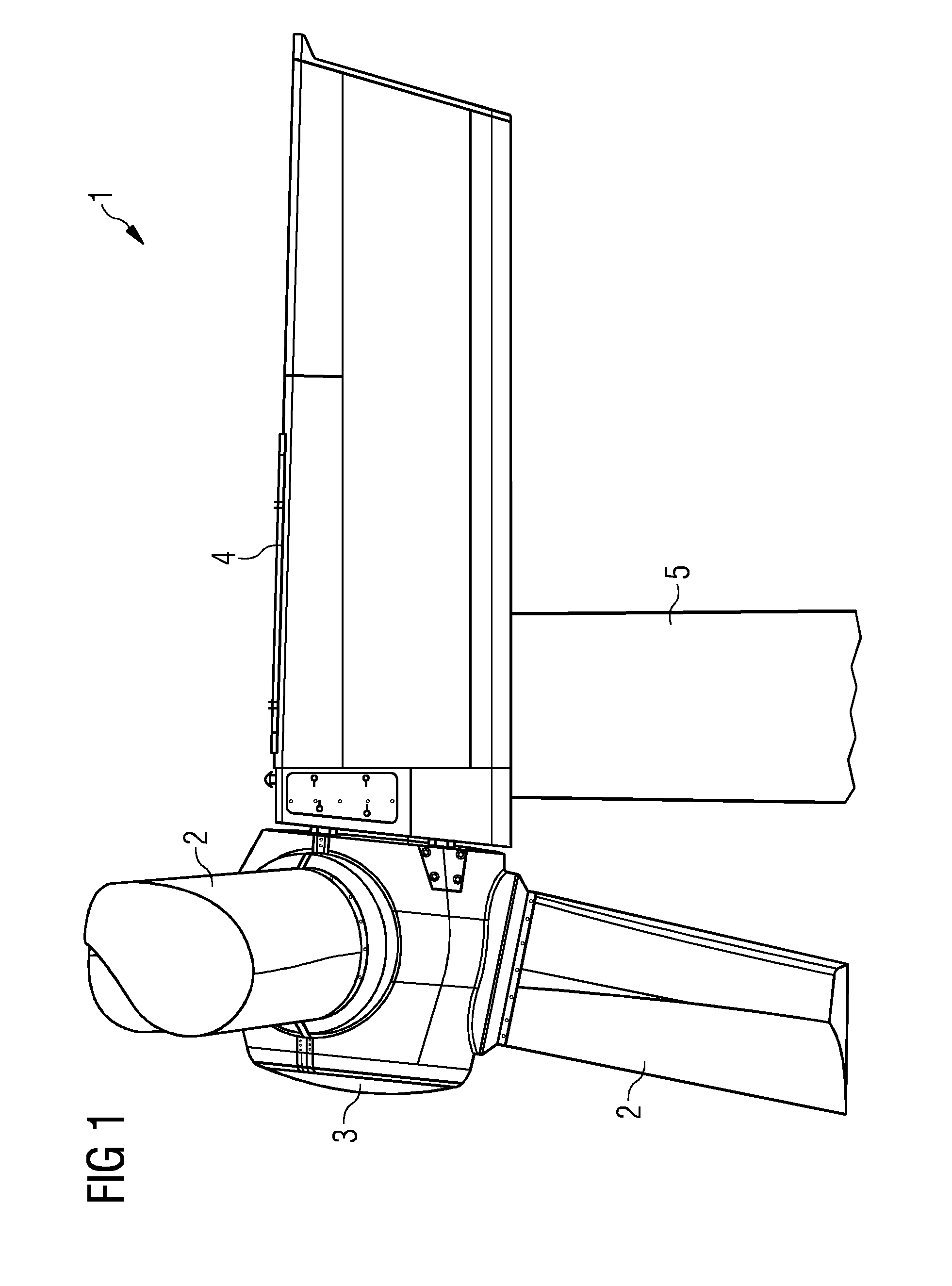
[0049]FIG. 1 shows a wind turbine generator system.[0050]FIG. 1 shows a wind turbine generator system 1. The wind turbine generator system 1 comprises a nacelle 4, which is rotatably arranged on a tower 5. A rotor hub 3 is rotatably attached to the nacelle 4. At least two rotor blades 2 are fastened to the rotor hub 3. In the operation of the wind turbine generator system 1, the wind acts on the rotor blades 2, which set the rotor hub 3 in rotation. The rotor blades 2 are attached to the rotor hub 3 in such a way that they are rotatable about its longitudinal axis.

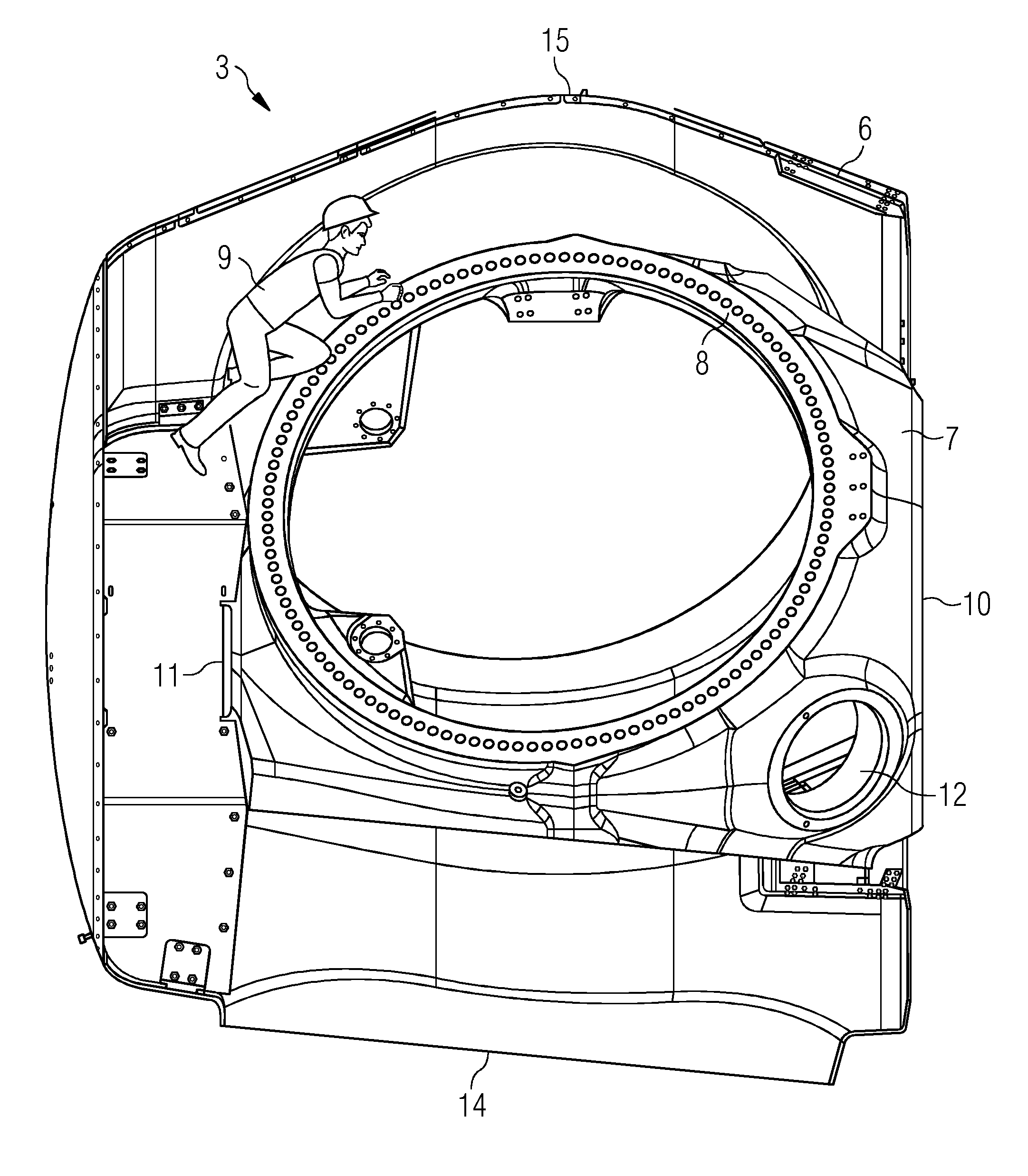
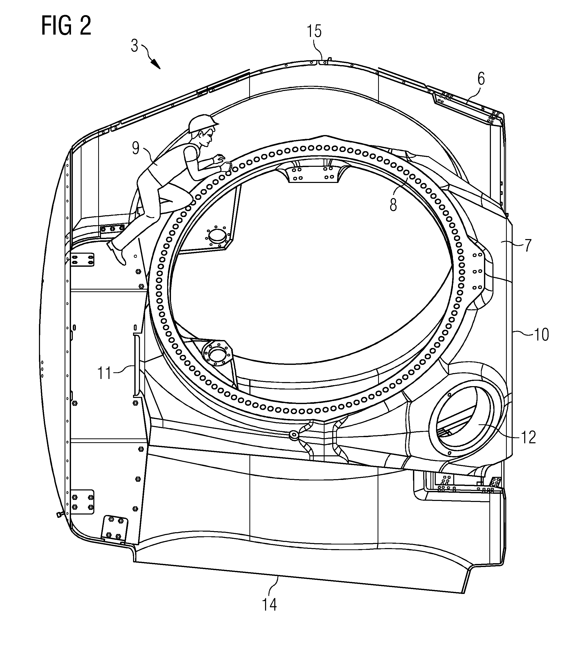
[0051]FIG. 2 shows the rotor hub of a wind turbine generator system.[0052]FIG. 2 shows the rotor hub 3 of a wind turbine generator system. The rotor hub 3 consists of a casting 7. The casting 7 has a flange 8, which is intended for receiving a rotor blade. The casting 7 of the rotor hub is surrounded by a rotor hub cladding 6.

[0053]The rotor hub 7 has at least two flanges 8 for receiving rotor blades. Between the two flang...


PUM


Abstract

A rotor hub of a wind turbine generator system is provided. A rotor hub of a wind turbine generator system comprises at least two connecting points for respectively receiving a rotor blade. The rotor hub is surrounded by a cladding, the cladding having at least two clearances respectively for a rotor blade. Between the two connecting points for receiving the rotor blades, the spacing between the rotor hub cladding and the rotor hub is set so as to create between the rotor hub cladding and the rotor hub a hollow space that is large enough to allow servicing work on the connecting point between the rotor blade and the rotor hub to be carried out by a worker from there.

Description

CROSS-REFERENCE TO RELATED APPLICATIONS[0001]This application claims priority to DE Application No. 102013214133.5, having a filing date of Jul. 18, 2013, the entire contents of which are hereby incorporated by reference.FIELD OF TECHNOLOGY[0002]The following relates to a rotor hub of a wind turbine generator system.BACKGROUND[0003]A wind turbine generator system often comprises at least two rotor blades, which are typically fastened to a rotor hub. The rotor hub ordinarily is rotatably attached to the nacelle of the wind turbine generator system. The nacelle of the wind turbine generator system may be rotatably arranged on a tower.[0004]A rotor blade may be connected to the rotor hub by way of a bearing, so that it is rotatable about its longitudinal axis. The rotor hub may have at least two receptacles for rotor blades.[0005]The rotor hub of a wind turbine generator system is usually produced as a casting. It often has a connecting point for fastening to the nacelle of the wind tu...

Claims


Application Information

Patent Timeline
IPC IPC(8): F03D11/00
CPCF03D11/0075F03D1/003F03D1/0691F03D80/50F03D80/88Y02E10/72
Inventor EBBESEN, HENNINGMUNK-HANSEN, THORKIL
Owner SIEMENS AG
Why Eureka
Try Eureka