Crown gear deceleration mechanism

a deceleration mechanism and gear technology, applied in the direction of gearing, toothed gearing, belt/chain/gearing, etc., can solve the problems of hard to enhance strength, rigidity, durability as a whole mechanism, and achieve the effect of strengthening strength, rigidity, and durability of the deceleration mechanism

Active Publication Date: 2015-01-22
FUKUSHIMA UNIVERSITY
View PDF4 Cites 21 Cited by
  • Summary
  • Abstract
  • Description
  • Claims
  • Application Information

AI Technical Summary

Benefits of technology

The present invention aims to improve the strength, rigidity, and durability of a crown gear deceleration mechanism.

Problems solved by technology

Therefore, there is a problem in that it is hard to enhance strength, rigidity, and durability as a whole mechanism.

Method used


Image

  • Crown gear deceleration mechanism
  • Crown gear deceleration mechanism
  • Crown gear deceleration mechanism

Examples


Embodiment Construction

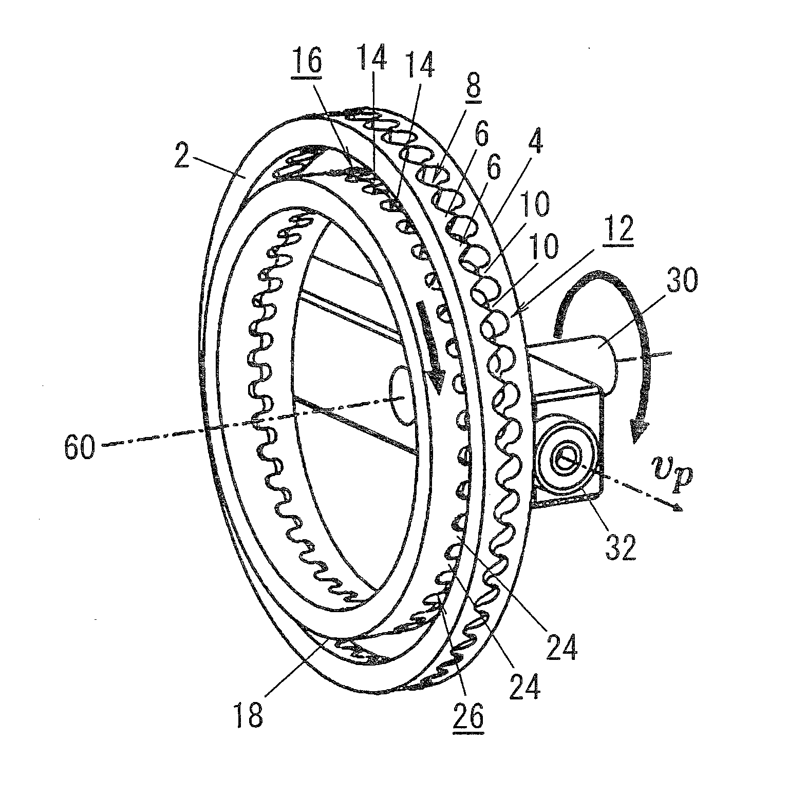
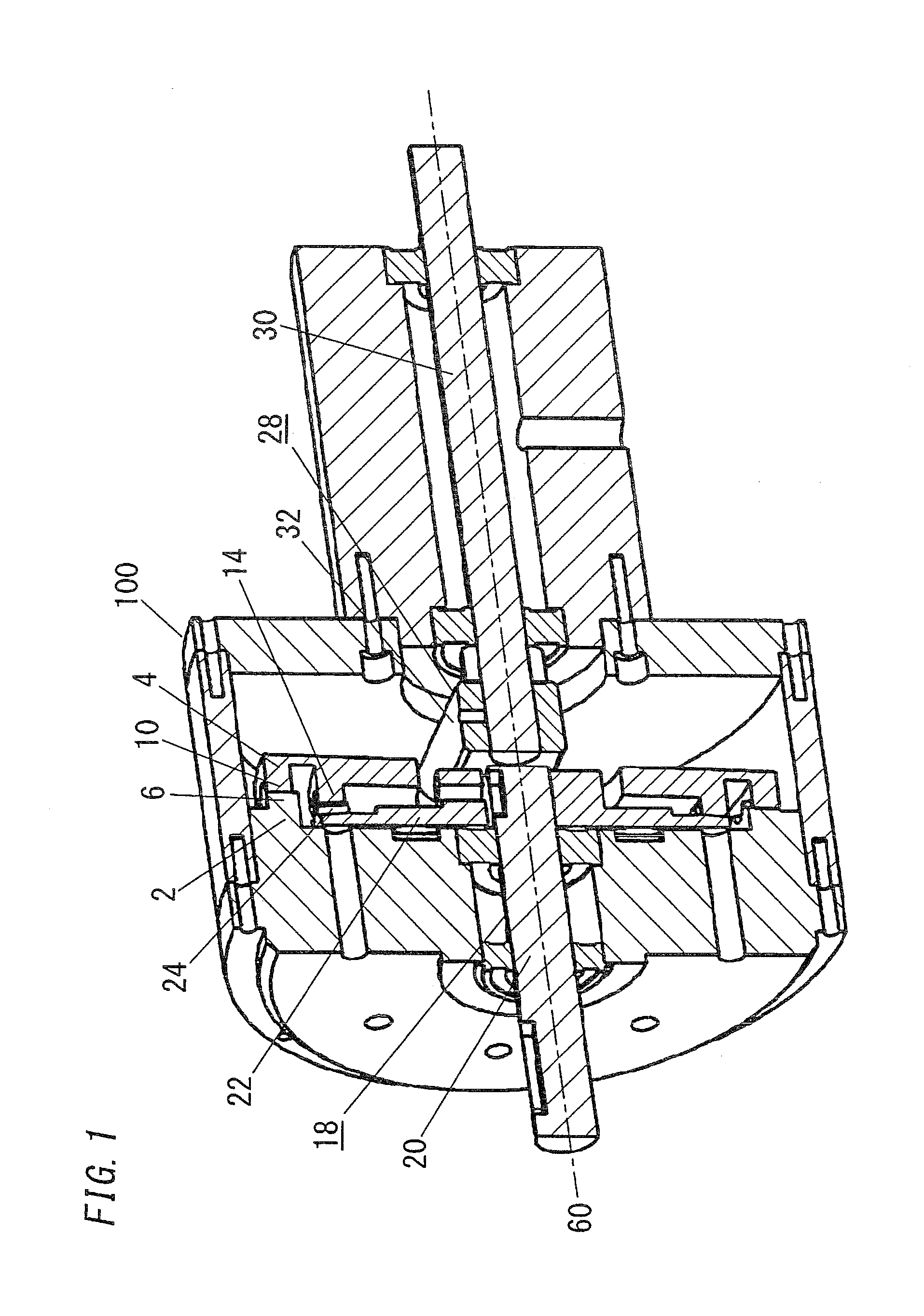
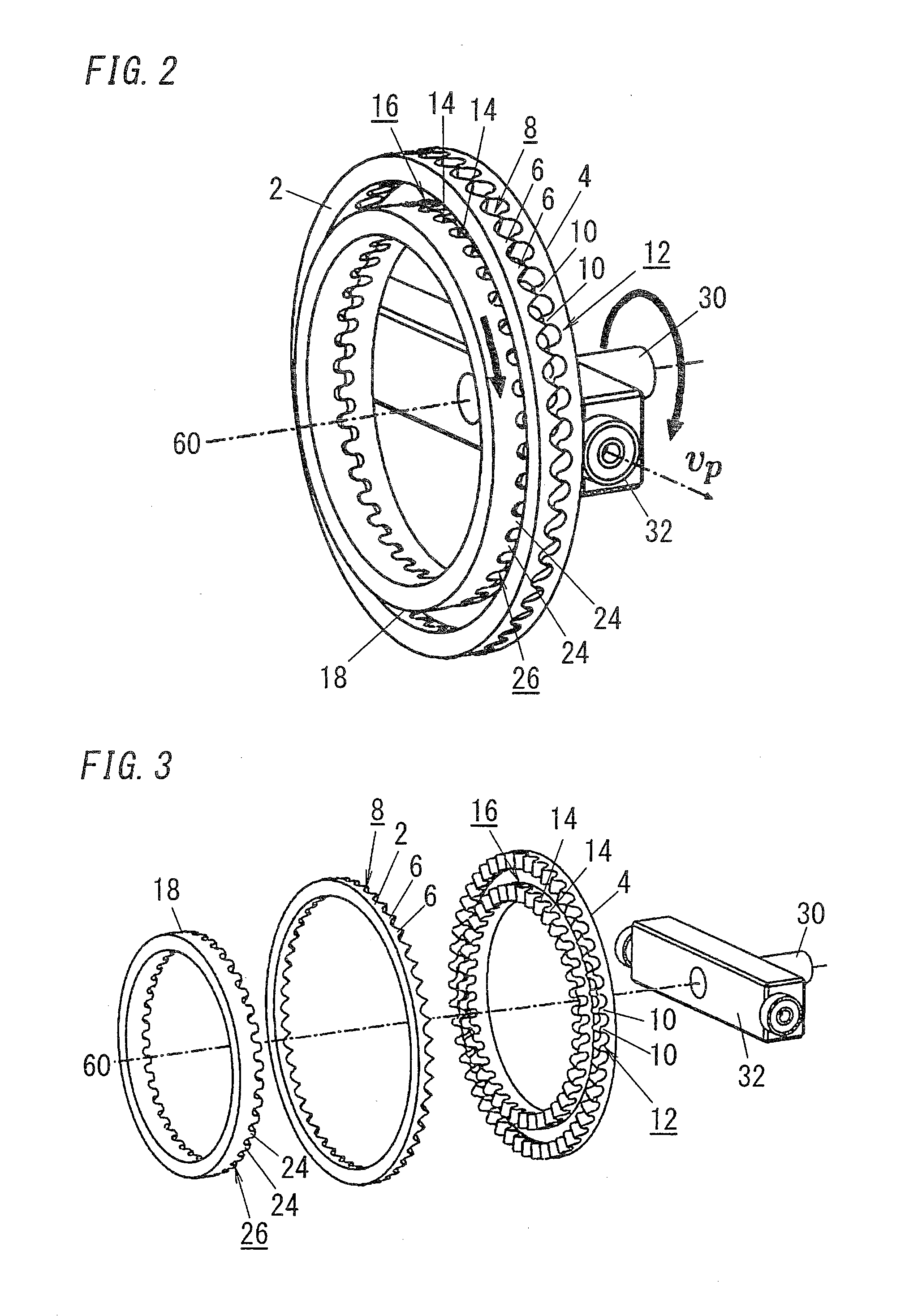
[0047]The present invention will be described based on an embodiment shown in the accompanying drawings. FIG. 1 shows a crown gear deceleration mechanism according to one embodiment of the present invention. FIGS. 2 and 3 show a main part of the crown gear deceleration mechanism.

[0048]The crown gear deceleration mechanism according to the present embodiment includes a stator 2 and a rotor 4. The stator 2 includes a fixed-side crown gear. The rotor 4 includes a movable-side crown gear performing a precession while being engaged with the stator 2. The stator 2 is fixed and arranged to a housing 100. The rotor 4 is arranged so as to be opposite to the stator 2 in the housing 100.

[0049]As shown in FIGS. 2 and 3, the stator 2 includes a plurality of stator teeth 6. The plurality of stator teeth 6 are circularly arranged on a surface of the stator 2, which is facing a side of the rotor 4. Here, N1S stator teeth 6 are arranged in a circumferential direction of the stator 2, and then a stat...


PUM


Abstract

A crown gear deceleration mechanism provided by the present invention includes: a stator including a crown gear; a rotor including another crown gear; and an output shaft coupled to the rotor. Stator includes a stator tooth row in which N1S stator teeth are circularly arranged. Rotor includes: a first rotor tooth row in which N1 teeth are arranged; and a second rotor tooth row in which N2 teeth are arranged. Output shaft includes an output tooth row in which N2S teeth are arranged. Rotor performs a precession while engaging the first rotor tooth row with the stator tooth row at places existing at both sides between which a devotion central line intervenes. Rotor transmits rotation to the output shaft while engaging the second rotor tooth row with the output tooth row at the places existing at both sides between which the devotion central line intervenes.

Description

TECHNICAL FIELD[0001]The present invention relates to a crown gear deceleration mechanism that is configured to transmit rotation by engagement between crown gears.BACKGROUND ART[0002]The inventors have proposed a crown gear deceleration mechanism that has a constitution shown in FIG. 25 as a deceleration mechanism capable of realizing high reduction ratio and low backlash, although it is a simple structure.[0003]As disclosed also in JP 4511635 B2, this crown gear deceleration mechanism includes a stator 102 and a rotor 104. The stator 102 is a crown gear that is fixed to an external member. The rotor 104 is another crown gear that is different from the stator 102. Then, the rotor 104 is pressed to a side of the stator 102 with a pressing mechanism 106 operated so as to rotate around an axis. The rotor 104 is engaged with the stator 102. In this case, both of teeth of the rotor 104 and teeth of the stator 102 have been set so that the rotor 104 inclines slightly to the stator 102 an...

Claims


Application Information

Patent Timeline
Patent Type & Authority Applications(United States)
IPC IPC(8): F16H1/32
CPCF16H1/32F16H1/321
Inventor TAKAHASHI, TAKAYUKISASAKI, HIROYUKI
Owner FUKUSHIMA UNIVERSITY
Why Eureka
Try Eureka