
Pneumatic tube carrier routing and tracking system

a technology of pneumatic tubes and carriers, applied in the field of pneumatic tube delivery systems, can solve the problems of unauthorized users accessing the carriers, miss-delivery of prescriptions, and time-consuming process of drug delivery and delivery

Active Publication Date: 2015-01-22
PEVCO SYST INT
View PDF3 Cites 12 Cited by
  • Summary
  • Abstract
  • Description
  • Claims
  • Application Information

AI Technical Summary

Benefits of technology

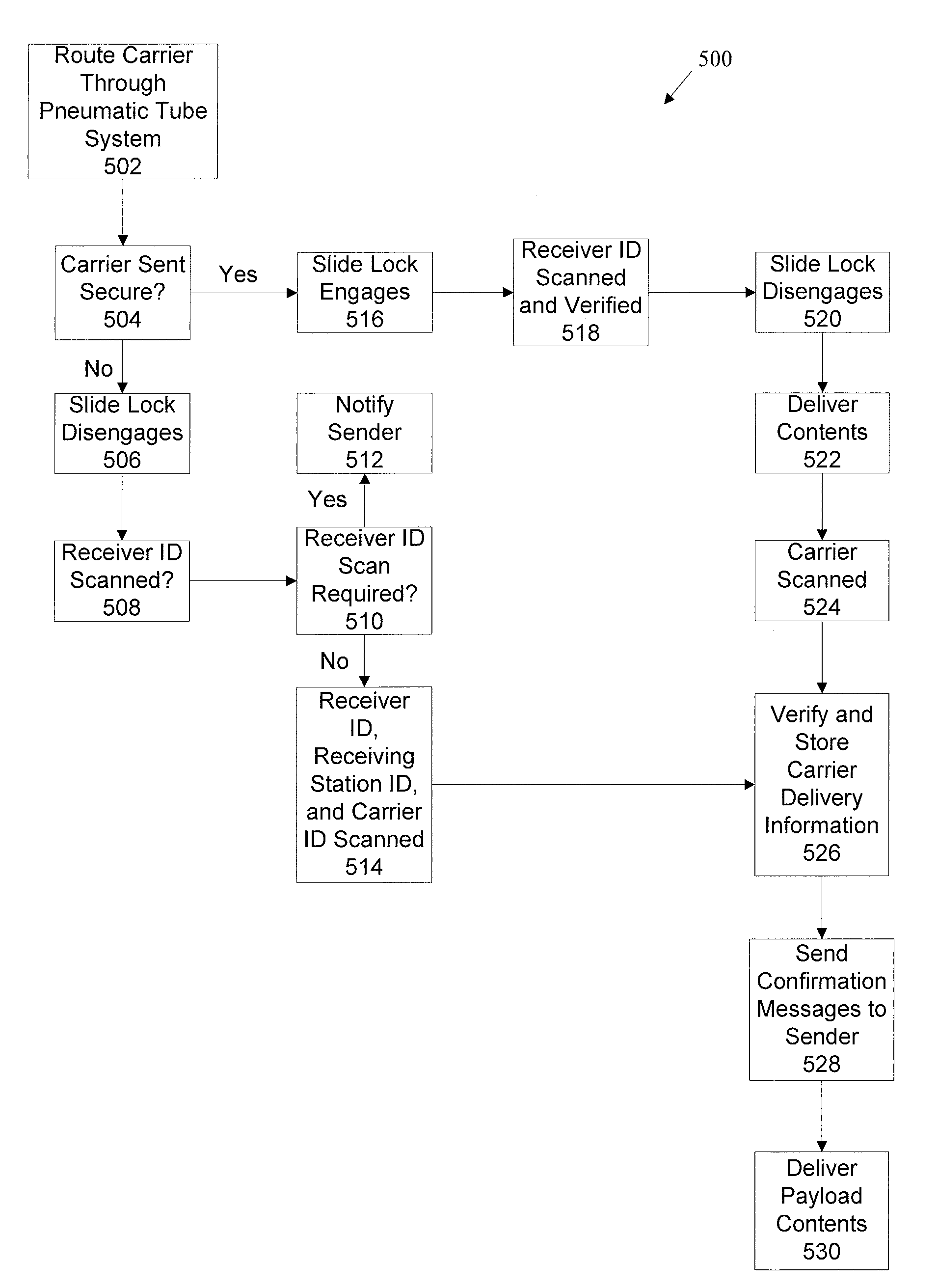
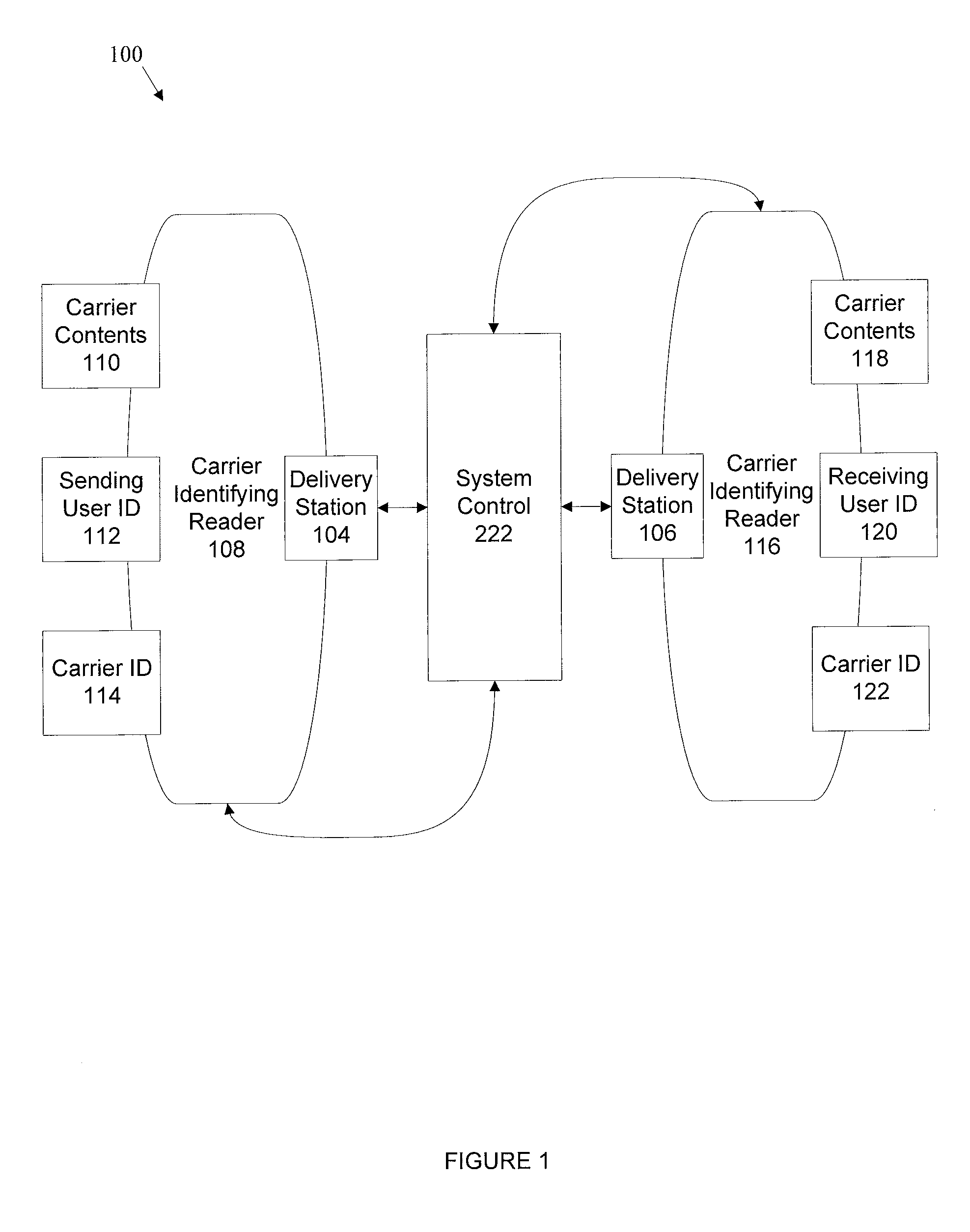
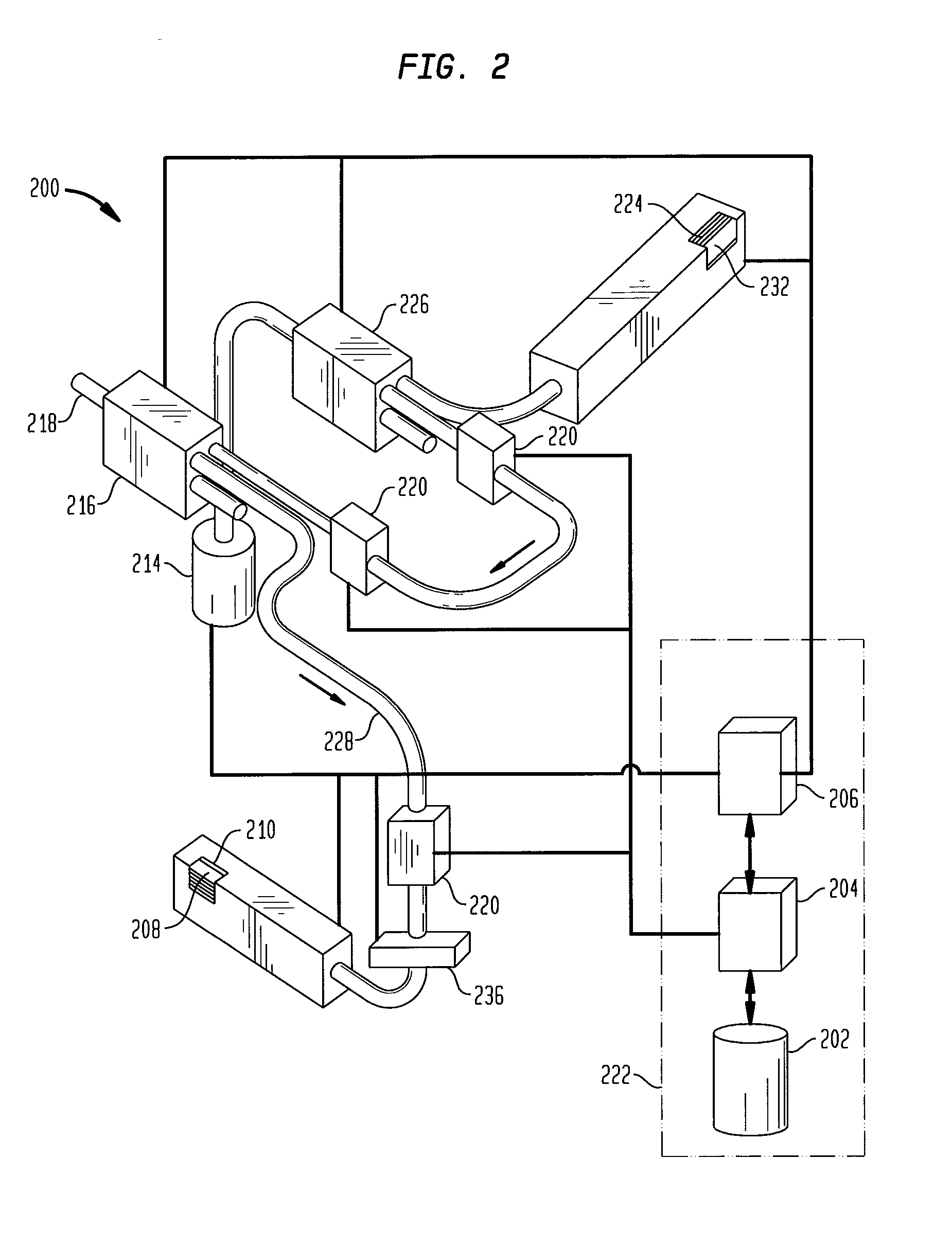
The present invention relates to a system for tracking carriers in a pneumatic tubing system. The technology involves using identifying tags to capture delivery and reception information of carriers as they move through the system. The system control module uses this information to route carriers through the pneumatic tubing system and deliver them to their destinations. The technical effects of the invention include improved efficiency, accuracy, and control over carrier movements within the system.

Problems solved by technology

In large institutional settings such as hospitals, the dispensing and delivery of drugs has become a time consuming process.
User error may occur during the identification of the room and patient resulting in miss-delivery of the prescription.
In addition, unauthorized users may have access to the carriers at the receiving station.

Method used


Image

  • Pneumatic tube carrier routing and tracking system
  • Pneumatic tube carrier routing and tracking system
  • Pneumatic tube carrier routing and tracking system

Examples


embodiment 600

[0063]Referring now to FIG. 6A, a diagram of the carrier 610 with a unique identifying, optically scannable, tag (i.e. a bar code) 620 according to an embodiment 600 of the present principles is shown. The bar code 620 may be disposed on any part of the carrier 610, enabling the inline identifying tag readers 220 to scan the bar code 620 and transmit the delivery information and reception information to the system control module 222.

embodiment 630

[0064]Referring now to FIG. 6B, a diagram of the carrier 610 with a unique identifying RFID tag 640 according to an embodiment 630 of the present principles is shown. The RFID tags 640 may be disposed on any part of the carrier 610, enabling the inline identifying tag readers 220 to scan the RFID tags 640 and transmit the delivery information and reception information to the system control module 222.

[0065]Referring now to FIGS. 7A and 7B, a handheld PDA 700 configured for use as an identifying tag reader and user interface according to an embodiment of the present principles is depicted. While the handheld PDA 700 is described as a useful embodiment of the present principles, it is only exemplary of an identifying tag reader that may be used. For example, a non-handheld PDA may be used, in addition to a touch key initialization module attached to a wall, etc.

[0066]The handheld PDA 700 is provided to capture and present data associated with sending and receiving pneumatic tube syste...


PUM


Abstract

A system and method provides for a pneumatic tube carrier routing and tracking system having a system control module that captures and presents tracking information associated with sending and receiving carriers. The pneumatic tube carrier tracking system comprises sending and receiving stations connected by pneumatic tubing, and which are configured to securely send carriers, with receiving users optionally being restricted from unauthorized access of carriers. The receiving station further comprises a plurality of receiving bins, each comprising a door for preventing access to the receiving bin by unauthorized users. The sending and receiving stations have identifying tag readers configured to scan identifier tags to read carrier delivery, carrier receipt and receiving user information. Destination and intended recipient information are entered at the sending station when sending a carrier and are transmitted to a system control module, which routably delivers and secures the carriers in response the destination and intended recipient information.

Description

CROSS-REFERENCE TO RELATED APPLICATIONS[0001]This application is a continuation-in-part of U.S. application Ser. No. 14 / 157,950, filed on Jan. 17, 2014, which is a divisional of U.S. application Ser. No. 13 / 372,571, filed on Feb. 14, 2012, now U.S. Pat. No. 8,700,207, issued on Apr. 15, 2014, which is a continuation-in-part of U.S. application Ser. No. 12 / 288,129, filed on Oct. 16, 2008, now U.S. Pat. No. 8,116,906, issued on Feb. 14, 2012, the entire contents of the entire chain of applications hereby being incorporated by reference.FIELD OF THE INVENTION[0002]The present principles generally relate to pneumatic tube delivery systems. More specifically, the present principles refer to a system and method for routing and tracking carriers and associated payloads in pneumatic tube delivery systems directly to an end user.BACKGROUND OF THE INVENTION[0003]In large institutional settings such as hospitals, the dispensing and delivery of drugs has become a time consuming process. In part...

Claims


Application Information

Patent Timeline
Patent Type & Authority Applications(United States)
IPC IPC(8): G06Q10/08B65G51/42
CPCG06Q10/08B65G51/42B65G51/46B65G51/36B65G51/04G06Q50/30B65G51/44G06Q50/10G06Q10/00G16C99/00G06Q50/40
Inventor VALERINO, SR., FREDRICK, M.
Owner PEVCO SYST INT
Learn More