

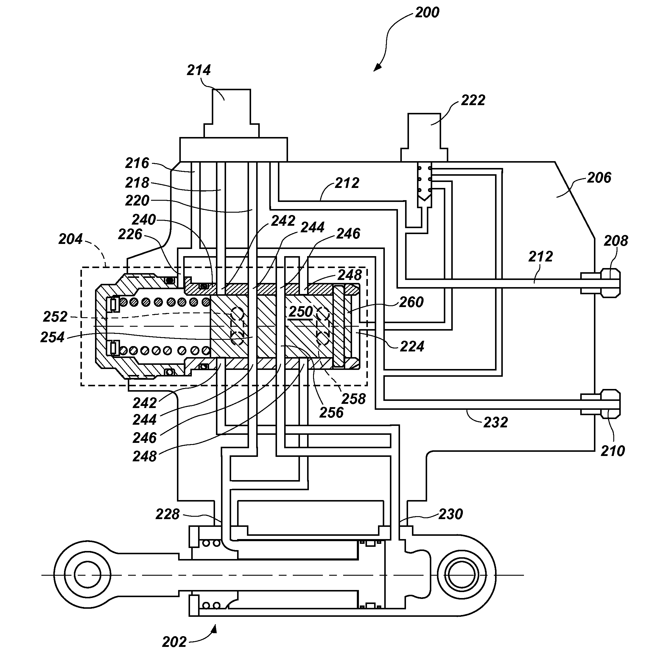
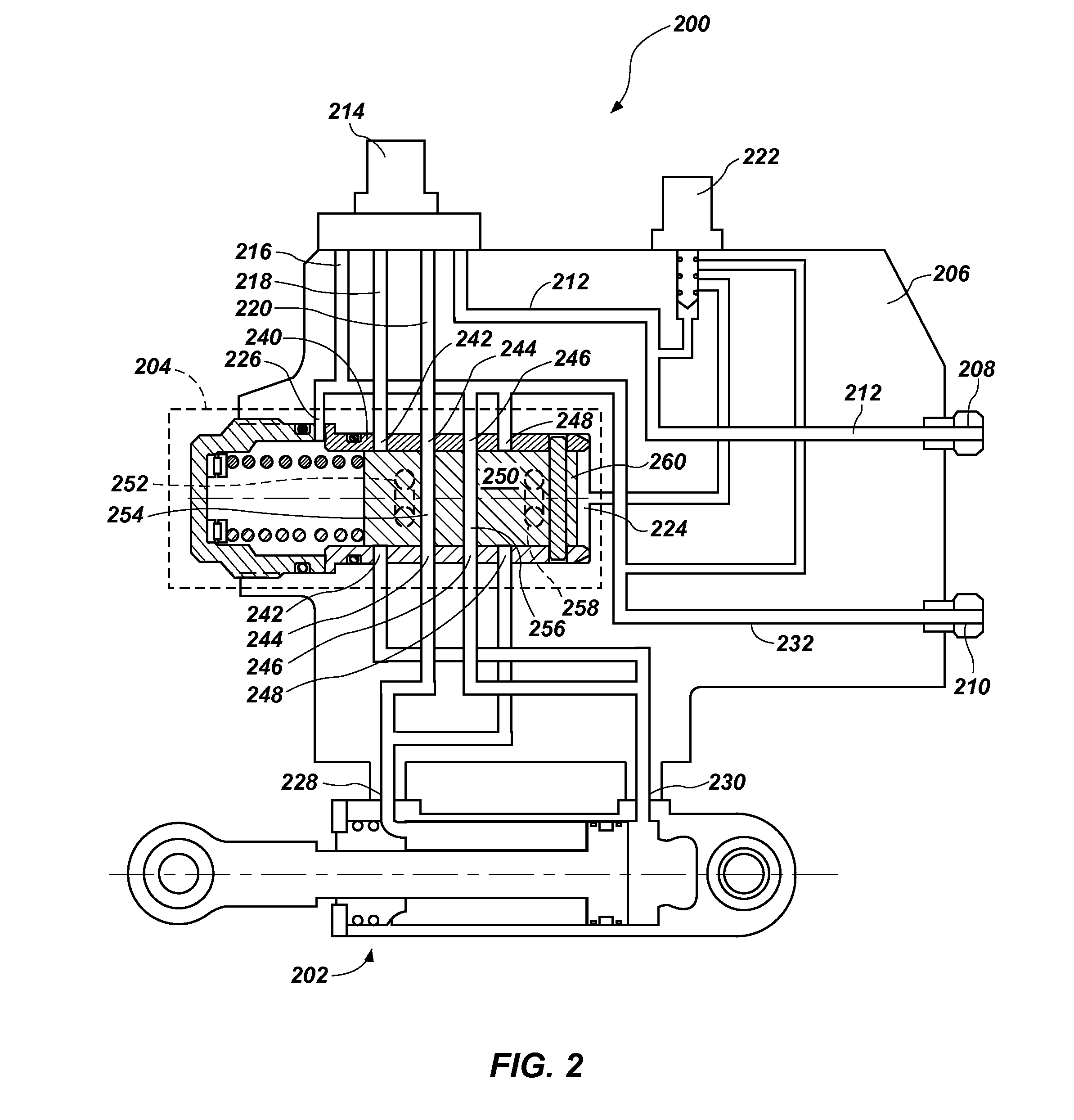
Hydraulic valve with helical actuator
a technology of hydraulic valves and actuators, applied in the field of hydraulic spool valves, can solve the problems of large and heavy current spool valve manifolds, and the type of valves also tend to be heavy, and achieve the effect of small and light weigh
- Summary
- Abstract
- Description
- Claims
- Application Information
AI Technical Summary
Benefits of technology
Problems solved by technology
Method used
Image

Examples
Embodiment Construction
[0025]Reference will now be made to exemplary embodiments illustrated in the drawings, and specific language will be used herein to describe the same. It will nevertheless be understood that no limitation of the scope of the invention is thereby intended. Alterations and further modifications of the inventive features illustrated herein, and additional applications of the principles of the inventions as illustrated herein, which would occur to one skilled in the relevant art and having possession of this disclosure, are to be considered within the scope of the invention.
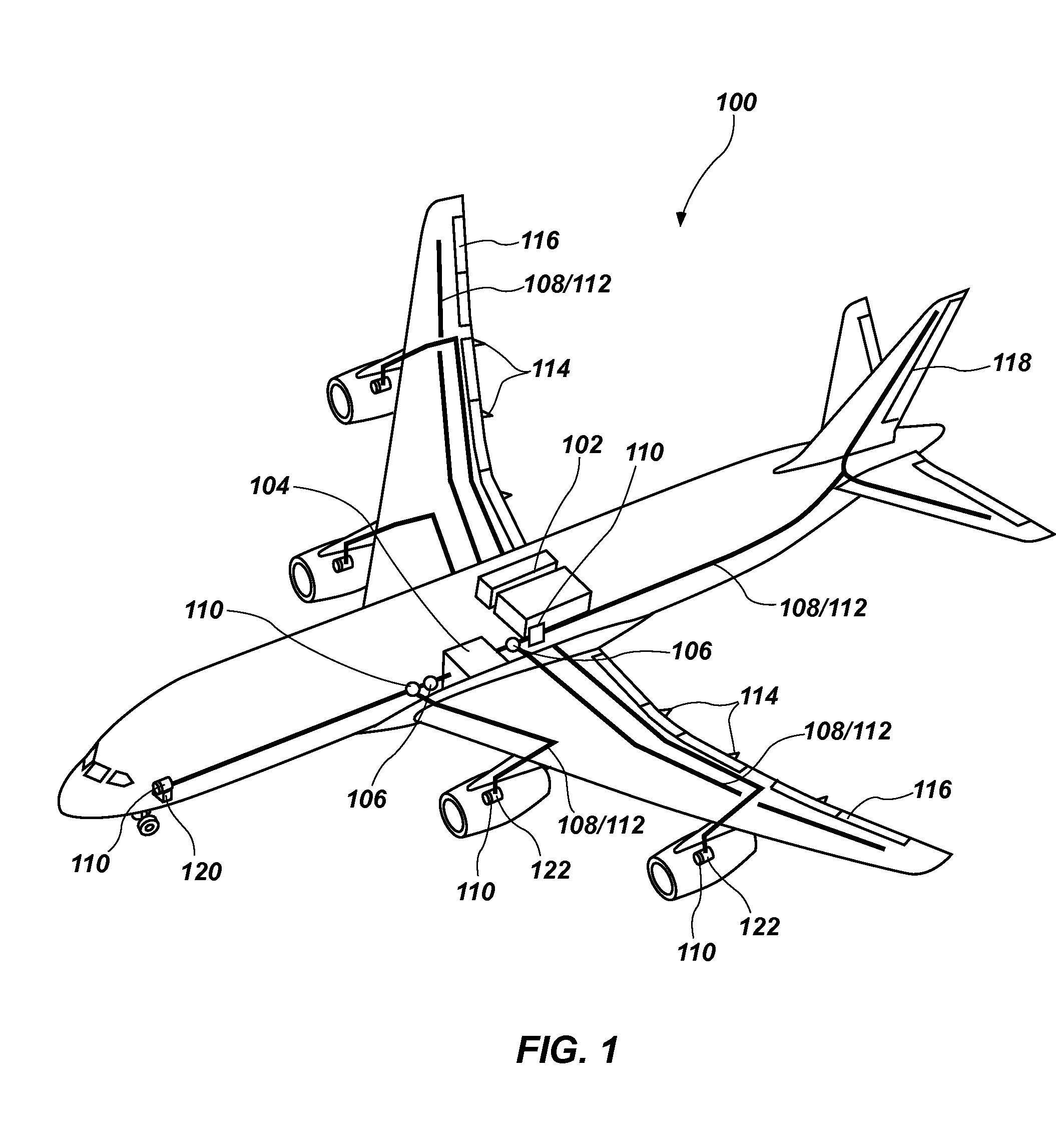
[0026]There are a wide variety of machines and devices that make use of hydraulic valves and hydraulic manifolds. These include vehicles, such as automobiles, aircraft and earth-moving equipment, as well as industrial machinery, for example. An aircraft 100 is shown in FIG. 1 as an example of a machine that includes a hydraulic system 102. In this schematic diagram of the hydraulic system of the aircraft, it can be s...
PUM
 Abstract
Description
Claims
Application Information