Integrated image erector and through-sight information display for telescope or other optical device

a technology of through-sight information display and optical device, which is applied in the field of integrated image erector and through-sight information display for telescope or other optical device, can solve the problems of adding to the size and weight achieve the effects of improving the battery life of the optical device, saving energy use, and being small and/or lighter

Inactive Publication Date: 2015-03-24
CUBIC CORP
View PDF5 Cites 3 Cited by
  • Summary
  • Abstract
  • Description
  • Claims
  • Application Information

AI Technical Summary

Benefits of technology

[0003]Techniques are disclosed for creating optical systems and devices that provide through-sight information while enabling the optical systems and devices to maintain a small, lightweight form factor. According to certain embodiments of the invention, an optical assembly can include a liquid-crystal display (LCD) disposed between the two prism elements of a Schmidt-Pechan prism at a focal plane of the optical assembly. This allows the LCD to be used to display information by blocking light passing through the optical assembly. Additionally, a light-emitting display, such as a backlit LCD, light-emitting diode (LED) display, or organic LED (OLED) display, can be coupled at a surface of one of the two prism elements of the Schmidt-Pechan prism to provide additional information in low-light environments.
[0010]Numerous benefits are achieved by way of the present invention over conventional techniques. For example, embodiments of the present invention enable an optical device to use a Schmidt-Pechan prism (or other split-prism) for image erection while providing additional through-sight information. This can allow for a smaller, cheaper, and / or lighter optical device. Additionally, because the LCD blocks the light passing through the optical device, it does not need to inject additional light into the system to be seen against the displayed image, saving on energy use and substantially increasing battery life for the optical device. Furthermore, a light-emitting display may be coupled with the Schmidt-Pechan prism at another location in the optical assembly, allowing for information to be seen on the displayed image of the optical device in low-light environments. These and other embodiments of the invention, along with many of its advantages and features, are described in more detail in conjunction with the text below and attached figures.

Problems solved by technology

Displaying both the information and the target, however, can present various technical challenges.
Folding the optical path with a Schmidt-Pechan prism is one way to both shorten the optical device and also turn the image right-side up, but inserting additional information into the optical path travelling through the optical device can require additional optical elements into the optical path, such as a beam splitter, which can add to the size and weight of the optical device.

Method used


Image

  • Integrated image erector and through-sight information display for telescope or other optical device
  • Integrated image erector and through-sight information display for telescope or other optical device
  • Integrated image erector and through-sight information display for telescope or other optical device

Examples


Embodiment Construction

[0018]The ensuing description provides embodiments only, and is not intended to limit the scope, applicability or configuration of the disclosure. Rather, the ensuing description of the embodiments will provide those skilled in the art with an enabling description for implementing an embodiment. It is understood that various changes may be made in the function and arrangement of elements without departing from the spirit and scope.

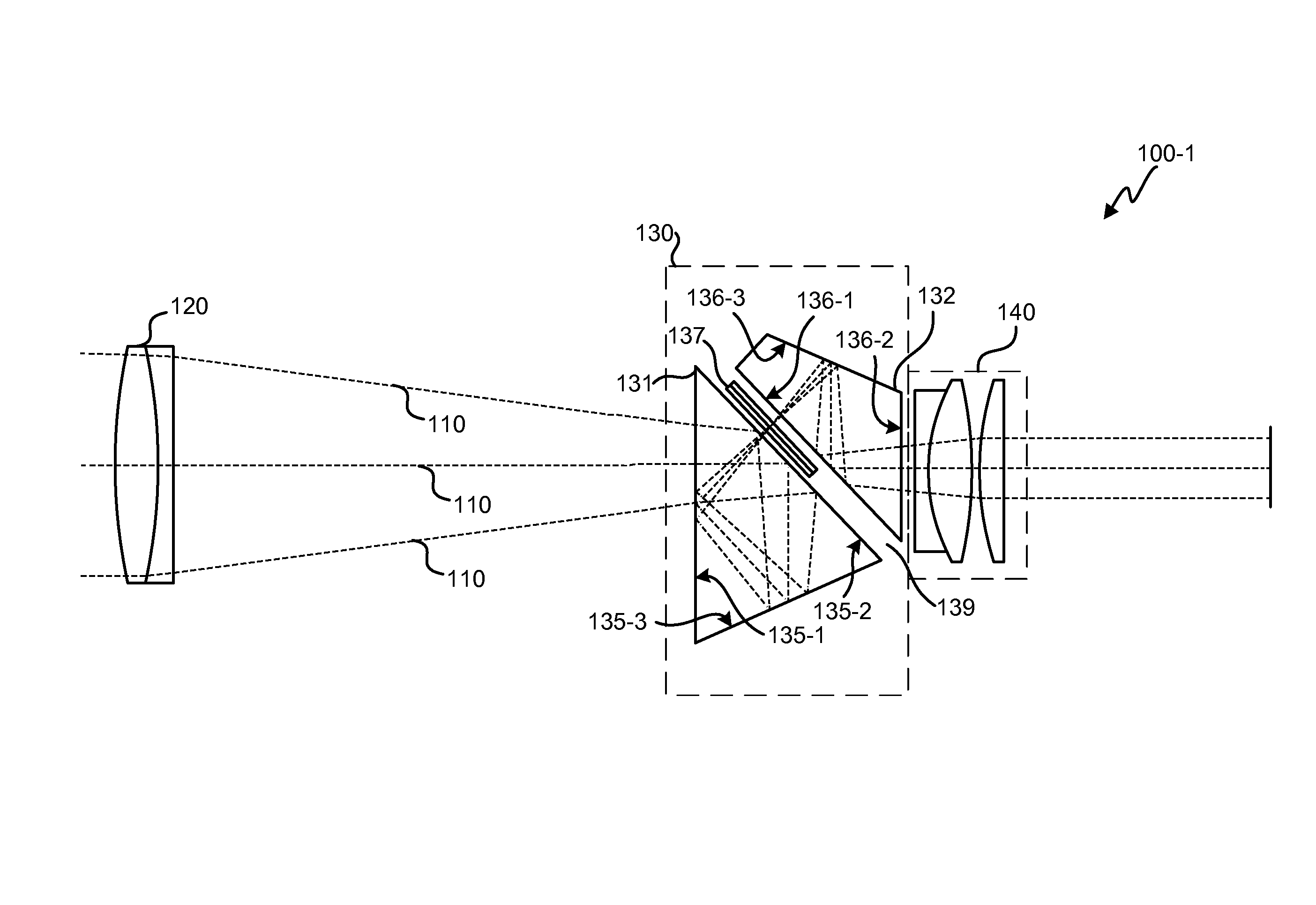
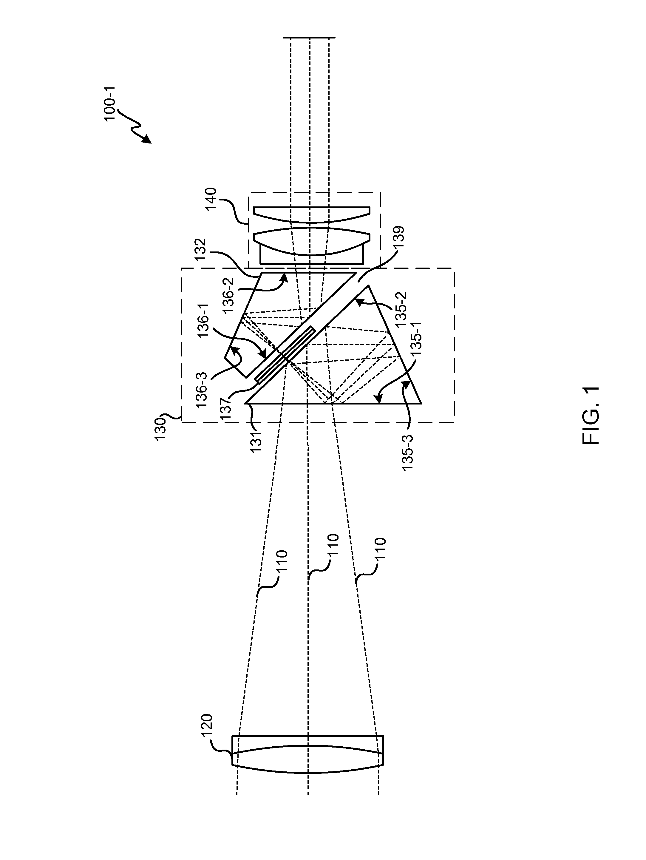
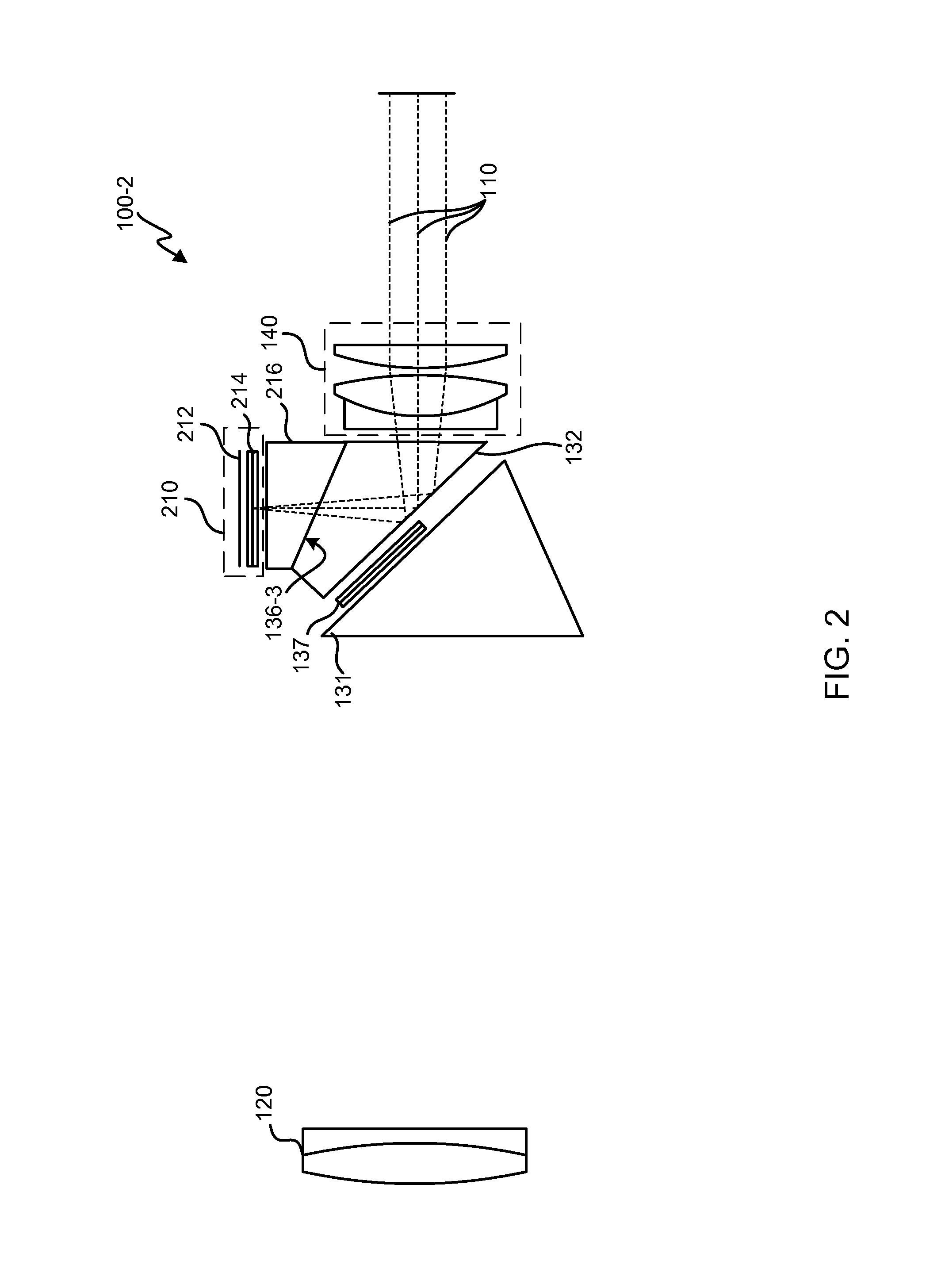
[0019]Modern optical devices can provide information in an image seen through an eyepiece of the optical devices. In addition to a target on which the optical device focused, for example, the optical device can display additional information through an eyepiece or viewfinder, such as information about the target, the environment, the optical device, and the like. Some optical devices provide the information separate from the image, such as below the image or in a blacked-out portion of the image. These optical devices can be easier to implement, but may be...


PUM

PropertyMeasurementUnit
distanceaaaaaaaaaa
refractive indexaaaaaaaaaa
aperture diametersaaaaaaaaaa

Abstract

Techniques are disclosed for creating optical systems and devices that provide through-sight information while enabling the optical systems and devices to maintain a small, lightweight form factor. According to certain embodiments of the invention, an optical assembly can include a liquid-crystal display (LCD) disposed between the two prism elements of a Schmidt-Pechan prism at a focal plane of the optical assembly. This allows the LCD to be used to display information by blocking light passing through the optical assembly. Additionally, a light-emitting display, such as a backlit LCD, light-emitting diode (LED) display, or organic LED (OLED) display, can be coupled at a surface of one of the two prism elements of the Schmidt-Pechan prism to provide additional information in low-light environments.

Description

CROSS-REFERENCES TO RELATED APPLICATIONS[0001]The present application claims benefit under 35 USC 119(e) of U.S. Provisional Application No. 61 / 380,166, filed on Sep. 3, 2010 of which the entire disclosure is incorporated herein by reference for all purposes.BACKGROUND[0002]In many optical devices information in addition to the image of the targeted object can be shown to a user looking into an eyepiece or viewfinder of the optical device. In the case of a laser rangefinder, for example, a distance to a target can be displayed along with an image of the target itself. Displaying both the information and the target, however, can present various technical challenges. Folding the optical path with a Schmidt-Pechan prism is one way to both shorten the optical device and also turn the image right-side up, but inserting additional information into the optical path travelling through the optical device can require additional optical elements into the optical path, such as a beam splitter, ...

Claims


Application Information

Patent Timeline
Patent Type & Authority Patents(United States)
IPC IPC(8): G02F1/13G02F1/1335G02B25/00
CPCG02F1/1335G02B25/001F41G1/00G02B17/045G02B23/10G02B27/026G02B27/143
Inventor TRISSEL, RICHARDMARYFIELD, TONYDADKAH, MAHYARROES, MICHAEL
Owner CUBIC CORP
Why Eureka
Try Eureka