Signal determination apparatus, optical projection apparatus, signal determination method, and storage meidum
a technology of optical projection apparatus and signal determination method, which is applied in the direction of video signal spatial resolution conversion, instruments, television systems, etc., can solve problems such as erroneously determining the format of input signals
- Summary
- Abstract
- Description
- Claims
- Application Information
AI Technical Summary
Benefits of technology
Problems solved by technology
Method used
Image

Examples
first example embodiment
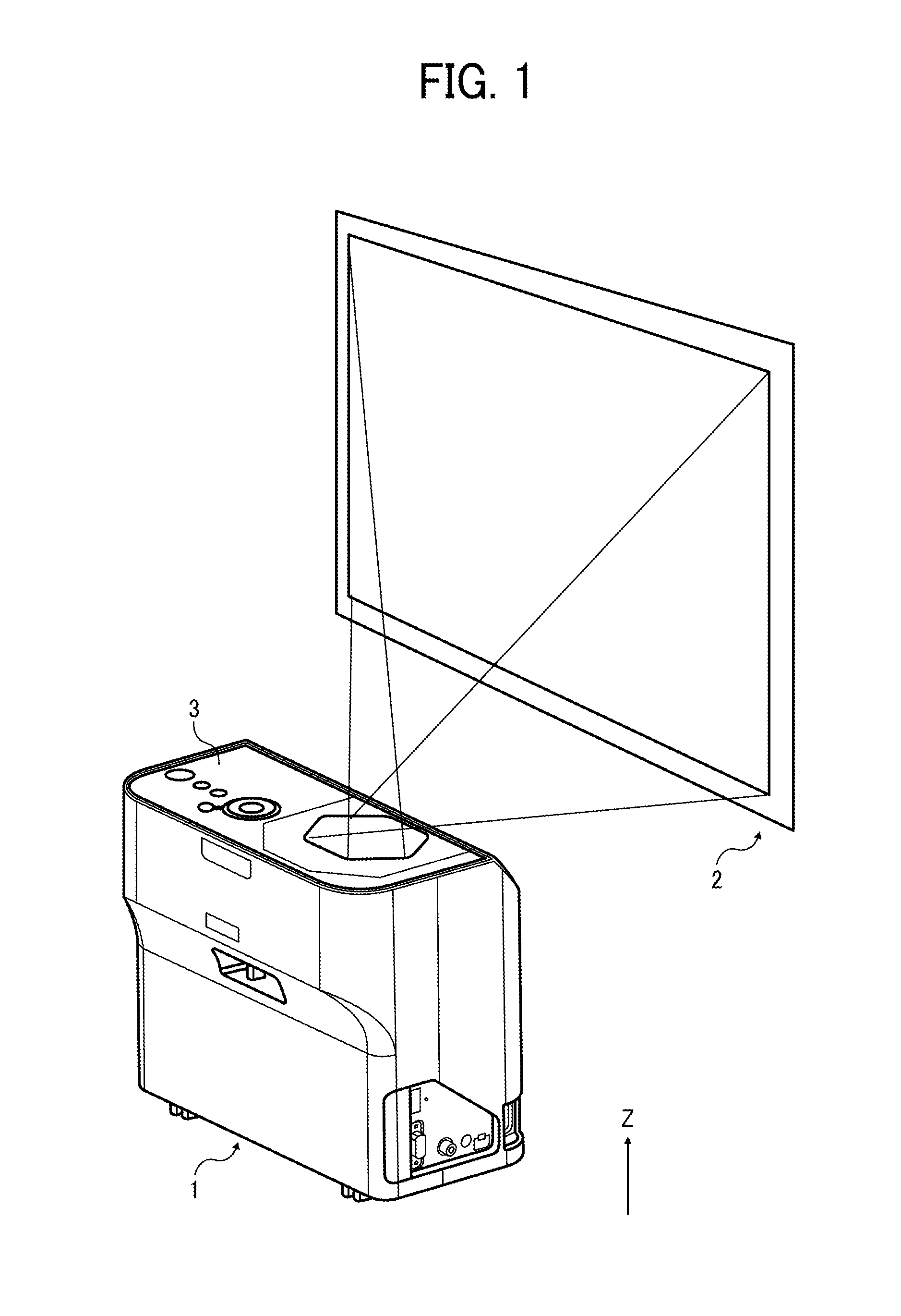
[0034]A description is given of a first example embodiment of the present invention with reference to drawings. FIG. 1 is a perspective view of a projector 1, used as an example of an optical projection apparatus of a first example embodiment, and a projection plane such as a screen 2. The projector 1 can generate images based on image data output from an image data output apparatus R (refer to FIG. 15) such as personal computers (PCs), video cameras, digital versatile disk (DVD) players, Blue ray players, tablet terminals, universal serial bus (USB) memories or the like, and projects the images on the screen 2 to display the images.
[0035]The projector 1 may be available as a liquid crystal projector having a liquid crystal panel enhancing resolution, a light source such as lamp enhancing light intensity by high efficient system, and such liquid crystal projector is available with lower prices. Further, the projector 1 may be available as a small light-weight projector using a micro...
second example embodiment
[0094]A signal determination apparatus of a second example embodiment has a configuration and control different from the first example embodiment as illustrated in FIGS. 17 and 18. As illustrated in FIG. 17, a second signal determination apparatus 100 includes, for example, the input unit 10a, a storage unit 10b, an estimation unit 100c, a decision part 100d, a determination part 100e, and the output unit 10e.
[0095]When parameter values (a, b) of the image signal (i.e., input signal) received from the input unit 10a match parameter values (a1, b1) or (a2, b2) included in Table A, the estimation unit 100c estimates that the format of the input signal is a format of one image signal (image signals 1 or 2) defined by parameter values (a1, b1), or a format of another one image signal (image signals 3 or 4) defined by parameter values (a2, b2), and transmits an estimation result (one image signal or another one image signal) and the input signal to the decision part 100d. Further, the e...
third example embodiment
[0116]A signal determination apparatus of a third example embodiment has a configuration and control different from the first and second example embodiments as illustrated in FIGS. 19 and 20.
[0117]As illustrated in FIG. 19, in the third example embodiment, a signal determination apparatus 200 includes, for example, the input unit 10a, a storage unit 200b, a determination part 200c, and the output unit 10e.
[0118]The storage unit 200b stores Table C storing parameter values (a1, b1, c1) of image signal 1, parameter values (a1, b1, c2) of image signal 2, parameter values (a2, b2, c1) of image signal 3, and parameter values (a2, b2, c2) of image signal 4.
[0119]The storage unit 200b may be a memory or a disk used as a storage or a carrier medium, in which data can be erased and written / re-written, or a read only memory or a disk used as a storage or a carrier medium.
[0120]Upon receiving an input signal from the input unit 10a, if parameter values (a, b, c) of the input signal match any ...
PUM
 Abstract
Description
Claims
Application Information
 - R&D
- Intellectual Property
- Life Sciences
- Materials
- Tech Scout
- Unparalleled Data Quality
- Higher Quality Content
- 60% Fewer Hallucinations
Browse by: Latest US Patents, China's latest patents, Technical Efficacy Thesaurus, Application Domain, Technology Topic, Popular Technical Reports.
© 2025 PatSnap. All rights reserved.Legal|Privacy policy|Modern Slavery Act Transparency Statement|Sitemap|About US| Contact US: help@patsnap.com