Hot water storage unit, relief device and method of making a hot water storage unit

a technology of relief device and hot water storage unit, which is applied in the direction of operating means/releasing devices of valves, lighting and heating apparatus, heating types, etc., can solve the problems of ptr valve, manufacturer cannot perform a pressure test of the vessel, and is susceptible to damag

Active Publication Date: 2015-02-05
AUSTRALIAN VALVE GROUP
View PDF15 Cites 13 Cited by
  • Summary
  • Abstract
  • Description
  • Claims
  • Application Information

AI Technical Summary

Benefits of technology

[0015]The present invention provides that a relief device may be factory-fitted at the time of manufacture of the hot water storage unit without exposing the relief device to damage whilst it is in transit, i.e. from the time of manufacture of the hot water storage unit until the time of installation at the required site. In addition, the present invention provides that installation by the installer is still possible, in the event that the manufacturer prefers to not factory-fit the relief device. Both options are available to the manufacturer under the present invention and either option may be adopted without any adaptation or modification being required to the relief device or remainder of the hot water storage unit.

Problems solved by technology

Firstly, having the PTR valve located outside the outer casing of conventional hot water storage units means that PTR valve projects out from the side of the otherwise even outer casing and is susceptible to damage when the hot water storage unit is in transit, i.e. from the time of manufacture of the hot water storage unit until the time of installation at the required site. For this reason, manufacturers do not usually factory-fit the PTR valve. Instead, the hot water storage unit leaves the factory without the PTR valve fitted. Manufacturers provide the PTR valve separately for later installation by the installer, e.g. a plumber, at the time of installation of the hot water storage unit at the required site, e.g. a domestic, commercial or other installation site.
In addition, because the hot water storage unit leaves the factory without the PTR valve fitted, the manufacturer cannot perform a pressure test of the vessel to provide quality assurance that the vessel meets the required operating standards since the water storage unit would have to leave the factory with the PTR valve fitted for such quality assurance to be validly given by the manufacturer.
Furthermore, problems can arise when the PTR valve is provided separately and is installed by the installer, e.g. a plumber, at the time of installation of the hot water storage unit at the required site.
This requires one or more attempts by the installer to connect the PTR valve, using different amounts of thread tape on the screw thread of the PTR valve, until the outlet of the drain is orientated downwardly, at a suitable angle, and the PTR valve is securely attached (i.e. that the connection between the PTR valve and the hot water storage unit does not leak, which itself cannot be assured until the hot water storage unit is actually operating, which is itself disadvantageous).
However, this process can be a time-consuming for the installer, requiring several attempts merely to properly connect the PTR valve with the hot water storage unit.
In addition to the time consumed, problems may also arise if the connection of the PTR valve with the hot water storage unit is over or under tightened.
Over-tightening may result in damage to components, such as the screw threads on the PTR valve or the hot water storage unit.
Under-tightening may result in improper sealing at the connection, with consequential leakage of water from the vessel.
Each of these may be perceived as a fault by the consumer, necessitating a service call from the consumer to the manufacturer or a service agent to properly connect or to replace the PTR valve.
This is inconvenient and an annoyance for the consumer and is time-consuming and costly for the manufacturer or service agent having to attend the service call.
A further disadvantage of having a substantial portion of the body of the PTR valve located outside the outer casing is that heat loss occurs from the heated water inside the vessel, through the body of PTR valve, and to the ambient air outside the outer casing.
Conventional hot water storage units suffer from another disadvantage in that, to accommodate the different thicknesses of insulation that may be used in different units, the probes (28) must be made in a range of lengths so that they are of sufficient length to extend into the water in the vessel (12).

Method used


Image

  • Hot water storage unit, relief device and method of making a hot water storage unit
  • Hot water storage unit, relief device and method of making a hot water storage unit
  • Hot water storage unit, relief device and method of making a hot water storage unit

Examples


second embodiment

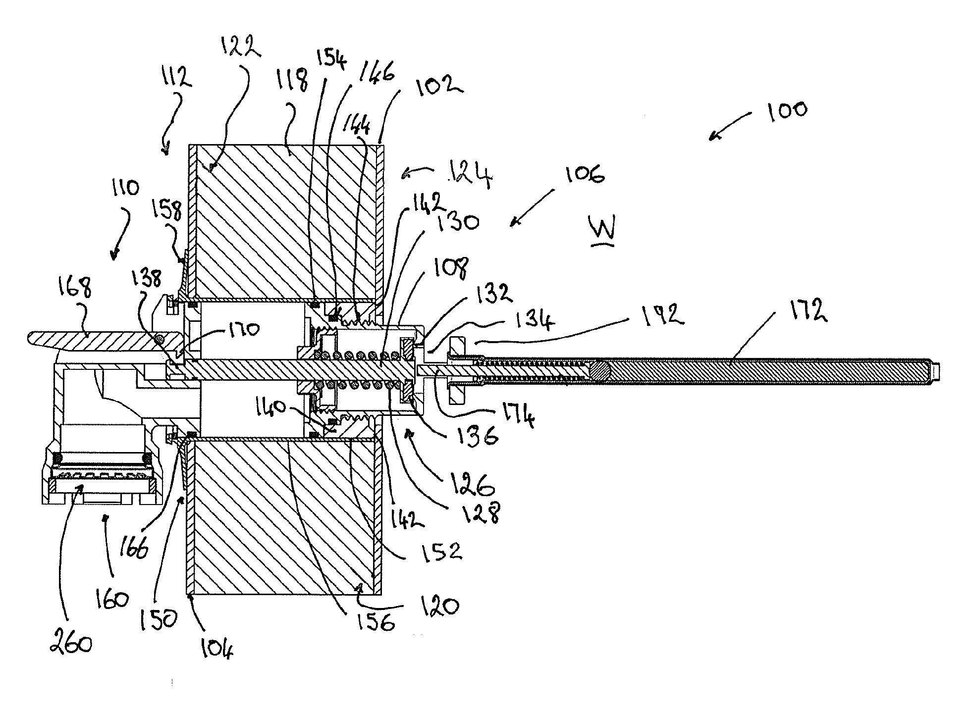
[0140]FIGS. 5A to 5H show various views of the relief device 200, showing as included in the hot water storage system 100 showing in FIG. 3B. However, since the relief device 200 is shown it is uninstalled condition, the various parts and features of the relief device 200 can be seen clearly in these views.

[0141]In that regard, some features of the relief device 200 (and also the relief device 106) can be more clearly seen in FIG. 5F. In particular, the head 176 of the stem 130 can be seen, which is provided at the end of the stem 130 that is provided in the housing 108. The head 176 supports the seal 136.

[0142]The stem 130 is provided with a seal 178 near the end portion 138 of the stem 130 that is remote from the head 176. The seal 178 may be an O-ring and is located in a groove 180 in the stem 130. The seal 178 is provided between the stem 130 and the drain 110, when the drain 110 is installed.

[0143]The relief device 200 further comprises a cap 182. The cap 182 is connected to th...

fourth embodiment

[0151]FIGS. 7A to 7E show a relief device 400 in which the seat 132 is formed by pressing a portion of the housing 402 of the relief device 400.

[0152]The relief device 400 illustrates how the housing 402 can be made in two parts 402a and 402b. The part 402a, which has the seat 132, is connected to a second part 402b. This connection can be by pressing together the housing parts 402a and 402b, as shown at 404.

[0153]The openings 310 are provided in the housing part 402b and these openings 310 form the outlet for the relief device 400.

[0154]The cap 312 is connected to the housing part 402b by screw threads in a similar manner to the screw threads 184 and 186 on the cap 182 and housing 108, respectively, of the relief devices 106 and 200.

[0155]The previous embodiments that have been described herein relate to a relief device that is sensitive to both pressure and temperature of the water inside the vessel 102. Those embodiments could be modified to form a relief device that is sensitive...


PUM


Abstract

A hot water storage unit 100 having a vessel 102, in which hot water is storable, an outer casing 104 enclosing the vessel 102, a hot water outlet 114 for heated water to exit from inside the vessel 102, and a relief device 106. The relief device 106 relieves excess pressure and/or temperature from inside the vessel 102 by allowing water to escape from inside the vessel 102 and exit from the relief device 106. The relief device 106 comprises a housing 108 containing the operational components of the relief device 106. The relief device 106 is removably retainable relative to the vessel 102 such that the housing 108 of the relief device 106 is located substantially behind the outer casing 104 of the hot water storage unit 100 on the inner side 122 of the outer casing 104.
The hot water storage unit 100 can be made by removably retaining the relief device 106 relative to the vessel 102 and placing the outer casing 104 around the vessel 102 so that the housing 108 of the relief device 106 is located substantially behind the outer casing 104, on the inner side 122 of the outer casing 104, after the outer casing 104 has been placed around the vessel 102.

Description

[0001]Throughout this specification, unless the context requires otherwise, the word “comprise” and variations such as “comprises”, “comprising” and “comprised” are to be understood to imply the presence of a stated integer or group of integers but not the exclusion of any other integer or group of integers.[0002]Throughout this specification, unless the context requires otherwise, the word “include” and variations such as “includes”, “including” and “included” are to be understood to imply the presence of a stated integer or group of integers but not the exclusion of any other integer or group of integers.[0003]The headings and subheadings in this specification are provided for convenience to assist the reader, and they are not to be interpreted so as to narrow or limit the scope of the disclosure in the description, claims, abstract or drawings.TECHNICAL FIELD[0004]The present invention relates to a hot water storage unit and a relief device for a hot water storage unit to relieve...

Claims


Application Information

Patent Timeline
Patent Type & Authority Applications(United States)
IPC IPC(8): F16K24/04F24D19/08F24D19/10
CPCF16K24/04F24D19/082F24D19/1051F16K17/048F16K17/0486F16K17/38F16K31/002F24D19/083F24D2220/0257F24H9/2007F28D20/0034F28F2265/12Y10T137/86324Y10T137/0486Y10T137/7837Y02E60/14
Inventor MORRIS, PETER JOHNWHITE, GARRY RODNEY
Owner AUSTRALIAN VALVE GROUP
Why Eureka
Try Eureka