Water Tempering System

a water tempering system and water tempering technology, which is applied in the direction of heating types, gas/liquid distribution and storage, applications, etc., can solve the problems of increasing the overall service and maintenance requirements of typical or standard watering tempering systems that are often found in high-rise buildings, and increasing the risk of possible scalding

Inactive Publication Date: 2015-02-05
2397593 ONTARIO
View PDF13 Cites 20 Cited by
  • Summary
  • Abstract
  • Description
  • Claims
  • Application Information

AI Technical Summary

Benefits of technology

[0007]In accordance with an exemplary embodiment of the present disclosure there is provided a water tempering system comprising a mixing tank having a first inlet for receiving fluid from a first water supply line at a first temperature, a second inlet for receiving fluid from a second water supply line, and a first outlet for discharging fluid from the mixing tank and delivering the fluid via a third water supply line at a predetermined second temperature; a variable frequency drive pump fluidly coupled to the second inlet for controlling the flow of fluid to the mixing tank through the second inlet; a control valve arranged in fluid communication with the variable frequency drive pump for controlling flow to the variable frequency drive pump; a control system for receiving temperature data associated with at least the third water supply line and transmitting said data for operably adjusting said variable frequency drive pump and said control valve to one of a set of predetermined operating conditions.
[0008]In accordance with another exemplary embodiment of the present disclosure there is provided a water tempering system comprising a first water supply line for supplying hot water at a first temperature; a second water supply line for supplying cold water; a third water supply line for delivering hot water at a second temperature from said water tempering system for use elsewhere in an overall water distribution system; a mixing tank having a first inlet in fluid communication with said first water supply line for receiving hot water at said first temperature, a second inlet in communication with said second water supply line for receiving cold water, and an outlet in fluid communication with said third water supply line for discharging hot water from said mixing tank at said second temperature; a variable frequency drive pump fluidly coupled to said second water supply line for controlling the flow of cold water to said second inlet of said mixing tank; and a control system for receiving data from at least said third water supply line and transmitting said data to said variable frequency drive pump.

Problems solved by technology

However, during periods of low usage or low demand on the water supply, for example during the overnight period, the main circulator pumps which pump the hot and cold water through the overall water distribution system are turned off or are not in use for energy saving purposes and a recirculation pump is often used to run hot water through the building.
Accordingly, during periods of low usage there is a risk that accurate mixing and accurate tempering of the domestic hot water will not occur raising the risk associated with possible scalding.
Furthermore, reduced flow through typical anti-scalding mixing valves tends to cause calcium build-up within the valve causing the valve to cease or fail which further increases the risk of scalding due to the tendency of the anti-scalding mixing valves to malfunction or fail.
Therefore, it has been found that the tendency for anti-scalding mixing valves to malfunction or fail due to improper mixing resulting from reduced flow rates through the valves and / or calcium build-up, increases the overall service and maintenance requirements of typical or standard watering tempering systems that are often found in high-rise buildings.

Method used


Image

  • Water Tempering System
  • Water Tempering System
  • Water Tempering System

Examples


Embodiment Construction

[0020]Reference will now be made in detail to exemplary implementations of the technology. The example embodiments are provided by way of explanation of the technology only and not as a limitation of the technology. It will be apparent to those skilled in the art that various modifications and variations can be made in the present technology. Thus, it is intended that the present technology cover such modifications and variations that come within the scope of the present technology.

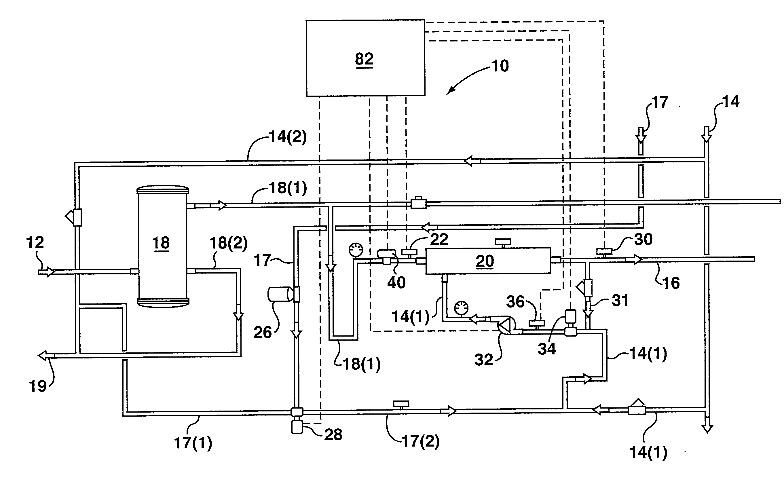
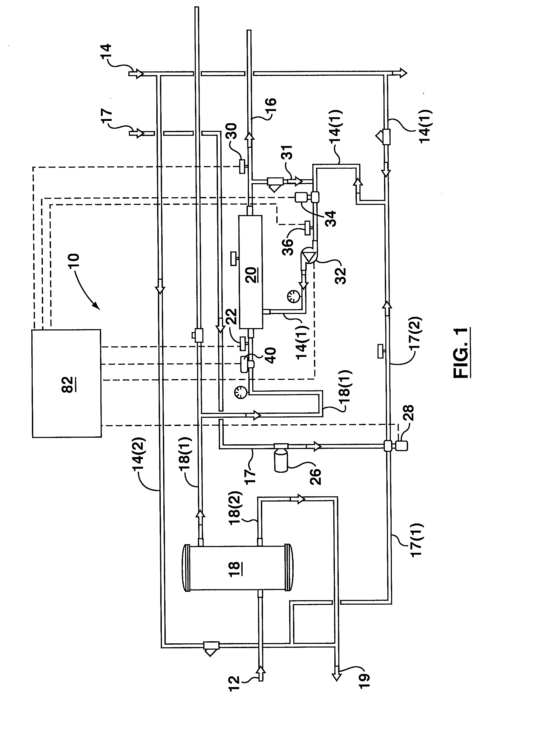
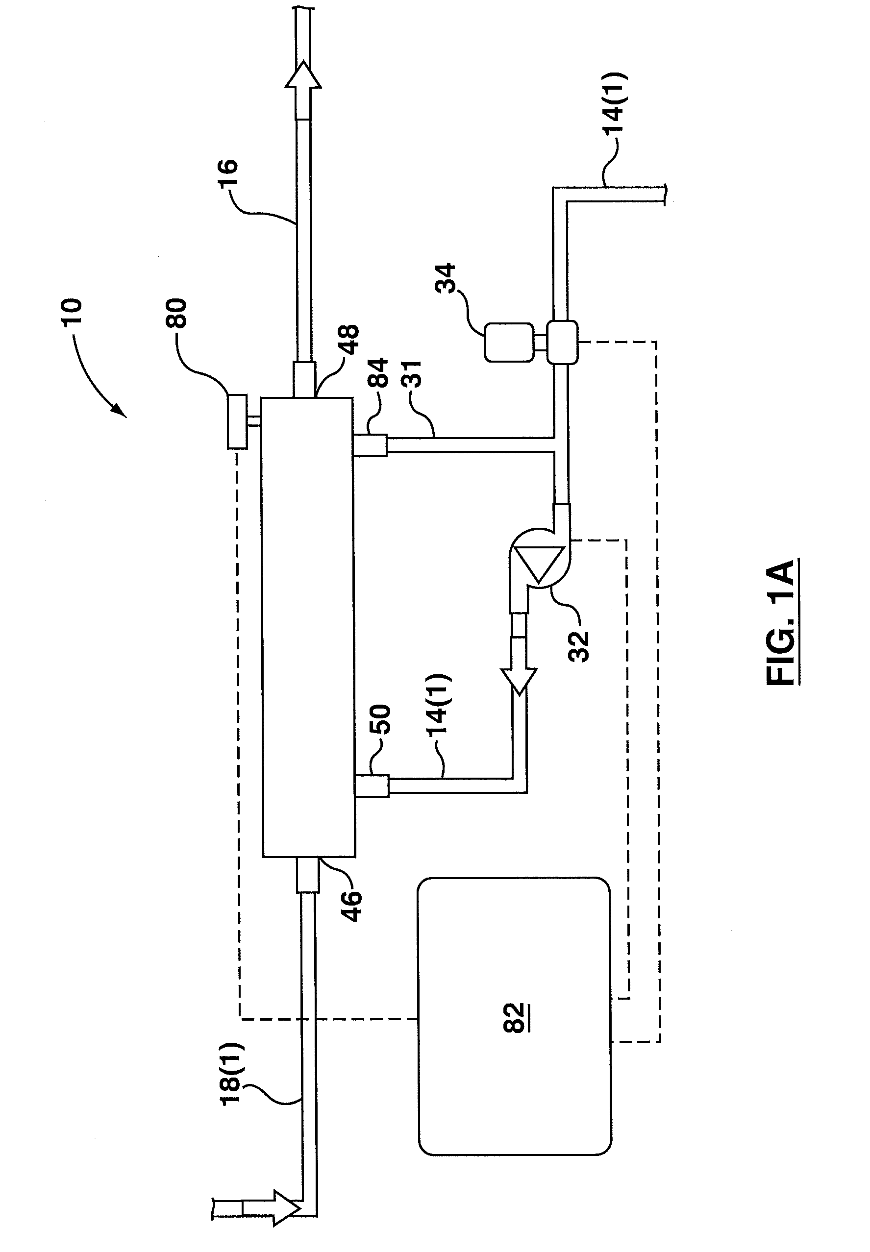
[0021]Referring now to FIG. 1 there is shown an exemplary embodiment of a water tempering system 10 according to the present disclosure. The water tempering system 10 is particularly designed for use in domestic hot water supply systems for high-rise buildings such as condominiums or apartment buildings in order to provide tempered hot water via a discharge water line or outflow fluid line at a selected and / or predetermined temperature so as to avoid potential risks / dangers associated with burns that can ...


PUM


Abstract

A water tempering system comprising a mixing tank located downstream from the main hot water storage tank, the mixing tank receiving a supply of hot water at a first temperature and a supply of cold water, the hot water and cold water supplies mixing within the mixing tank to provide a source of tempered hot water at a reduced, second temperature that is discharged from the mixing tank for distribution and use within an overall system. The amount of cold water directed to the mixing tank is controlled by a variable frequency drive pump which can adjust depending on system demands to ensure that sufficient cold water is directed to the mixing tank to ensure adequate mixing occurs to bring the temperature of the hot water to the second reduced temperature even during periods of low demand.

Description

CROSS-REFERENCE TO RELATED APPLICATIONS[0001]This application claims priority to and the benefit of U.S. Provisional Patent Application No. 61 / 859,948 filed Jul. 30, 2013 under the title WATER TEMPERING SYSTEM and U.S. Provisional Patent Application No. 61 / 910,174 filed Nov. 29, 2013 under the title WATER TEMPERING SYSTEM. The content of the above-noted provisional patent applications are hereby expressly incorporated by reference into the detailed description of the present application.TECHNICAL FIELD[0002]The invention relates primarily to a water tempering system. In particular, the invention relates to a water tempering system for the domestic hot water supply for incorporation into the overall water distribution system of buildings.BACKGROUND[0003]In general, building code guidelines for high rise condominium or apartment buildings, for example, require that domestic hot water enter the individual units or suites at a specific temperature in order to avoid potential scalding. F...

Claims


Application Information

Patent Timeline
Patent Type & Authority Applications(United States)
IPC IPC(8): F17D3/01
CPCF17D3/01E03B7/04E03B7/071E03C1/041F24D3/1091F24D17/0073Y10T137/85986Y02A20/15
Inventor JEBRAN, NASSIMMAZZULLO, LOUIEMAZZULLO, FRANKBASKOVIC, BERNARD
Owner 2397593 ONTARIO
Why Eureka
Try Eureka