
Casing filling tool

Active Publication Date: 2015-02-05
NABORS DRILLING TECH USA INC
View PDF3 Cites 1 Cited by
  • Summary
  • Abstract
  • Description
  • Claims
  • Application Information

AI Technical Summary

Benefits of technology

The patent describes a tubular filling tool that is used in drilling mineral extraction systems. The tool has a conductor pipe and a diffuser block that receives the filling fluid from the conductor pipe. The diffuser block has multiple fluid passages that create a swirl flow pattern in the fluid as it flows through the tool. This swirl flow pattern helps to improve the quality of the filling process. The tool also has blades that extend out from the conductor pipe, which helps to stabilize the fluid flow during the process. Overall, the tool design helps to increase the efficiency and effectiveness of the drilling process.

Problems solved by technology

Unfortunately, the filling process can be lengthy, thereby increasing the costs associated with the filling process.
However, increasing the speed of filling the string of tubular with the filling fluid can undesirably lead to aeration of the filling fluid.

Method used


Image

  • Casing filling tool
  • Casing filling tool
  • Casing filling tool

Examples


Embodiment Construction

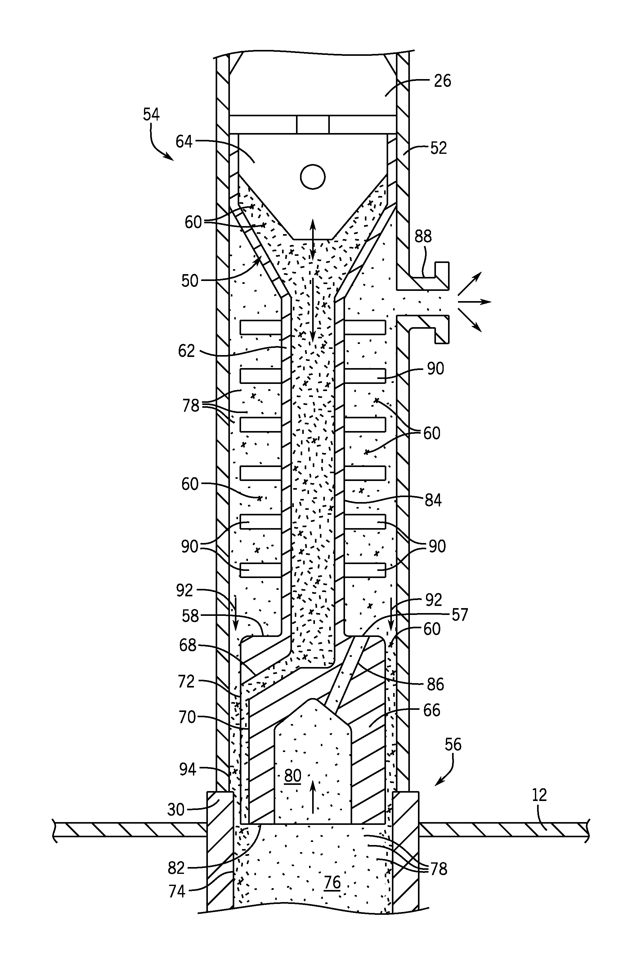
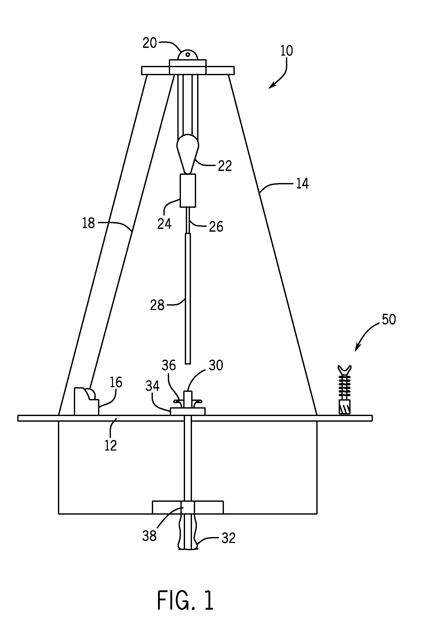
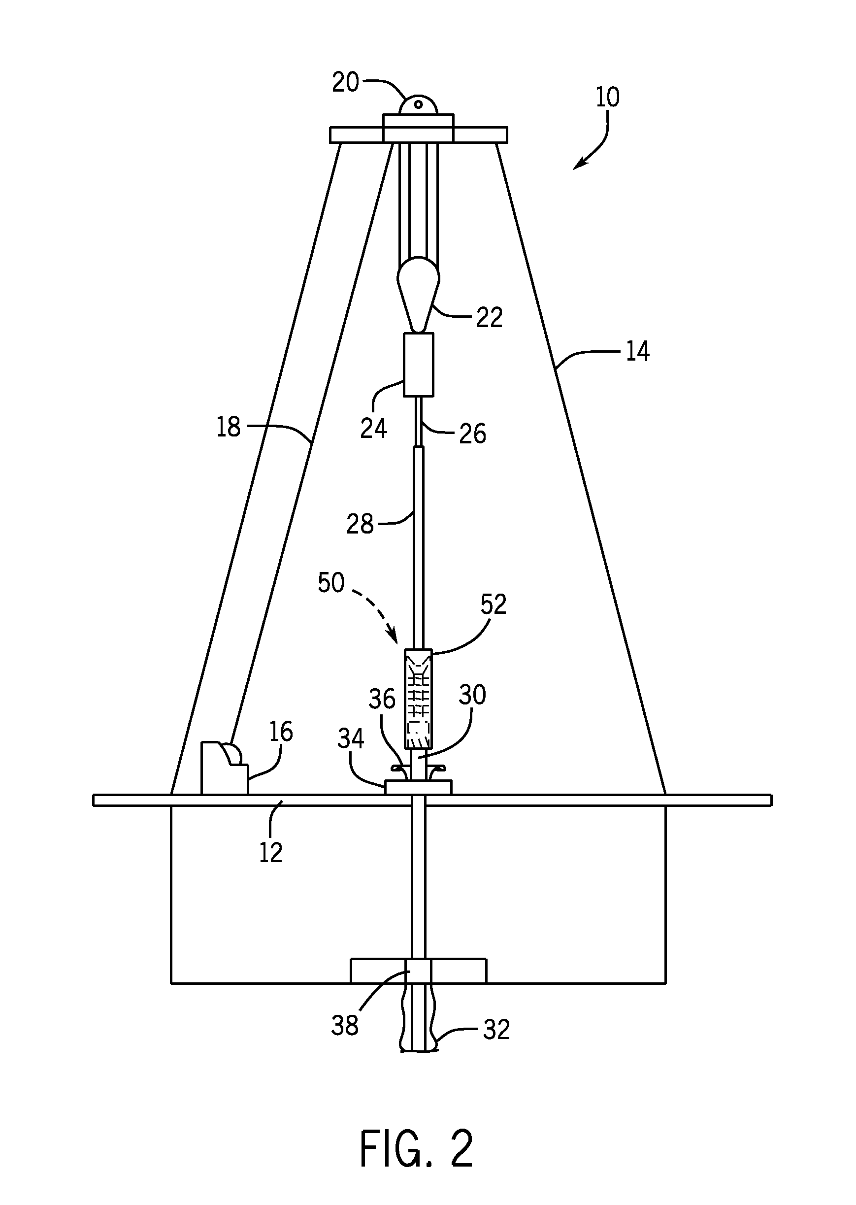
[0013]Embodiments of the present disclosure are directed toward a filling tool for filling casing or other tubular with a filling fluid. More specifically, during a filling process associated with running or landed casing, a filling tool may be used to increase the speed of filling the casing or tubular with filling fluid. Additionally, the filling tool may be configured to reduce aeration of the filling fluid during the filling process and / or separate entrained filling fluid from air exiting the casing during the filling process.

[0014]As discussed in detail below, in one embodiment, the filling tool includes a conductor pipe that flows filling fluid to a diffuser block of the filling tool. Thereafter, the diffuser block generates a swirl, vortex, or other helical flow pattern in the filling fluid as the filling fluid enters the casing or tubular. In this manner, the filling fluid may more completely travel downward against an inner diameter of the casing or tubular, thereby reducin...


PUM


Abstract

Present embodiments are directed to a tubular filling tool. In certain embodiments, the tubular filling tool includes a conductor pipe configured to receive a filling fluid flow from a top drive and a diffuser block communicatively coupled to the conductor pipe and configured to receive the filling fluid flow from the conductor pipe, wherein the diffuser block comprises a plurality of fluid passages extending to external passages formed in an outer diameter of the diffuser block and configured to facilitate passage of the filling fluid flow to the external passages from within the diffuser block, wherein the external passages are configured to generate a swirl flow pattern in the filling fluid flow during a tubular filling process.

Description

BACKGROUND[0001]The present disclosure relates generally to the field of drilling and processing of wells, and, more particularly, to a system and method for filling casing during a casing process, a drilling process, or another type of well processing operation.[0002]In conventional oil and gas operations, a well is typically drilled to a desired depth with a drill string, which includes drill pipe and a drilling bottom hole assembly. Once the desired depth is reached, the drill string is removed from the hole and casing is run into the vacant hole. Casing may be defined as pipe or tubular that is placed in a well to prevent the well from caving in, to contain fluids, and to assist with efficient extraction of product. Tubular may be defined as including drill pipe, casing, or any other type of tubular utilized in drilling or well processing operations.[0003]During drilling and casing running operations, a string of tubular (e.g., drill pipe or casing) is typically held by slips mo...

Claims


Application Information

Patent Timeline
IPC IPC(8): E21B41/00E21B21/14
CPCE21B21/14E21B41/00E21B34/06E21B43/10E21B21/106E21B21/10
Inventor NIKIFORUK, KEVIN JAMES
Owner NABORS DRILLING TECH USA INC
Learn More