
Lower drill tool for precision forming of openings in a bracket, and methods of use

Pending Publication Date: 2021-08-12
J R AUTOMATION TECH
View PDF5 Cites 0 Cited by
  • Summary
  • Abstract
  • Description
  • Claims
  • Application Information

AI Technical Summary

Benefits of technology

The patent is about a drill system that has an upper drill tool and a lower drill tool. The lower drill tool has a central body with drill bit bores, a centering nub, and a biasing member. The drill system also includes a bracket that can be attached to the lower drill tool. The upper drill tool has a central chuck and a lower component. The lower drill tool can be used with the upper drill tool, and they both work together to hold a drill bit and keep it in the correct position. The drill system is designed to make it easy to hold and use a drill bit. The technical effects of the patent are improved drilling efficiency and ease of use.

Problems solved by technology

The formation of rivet openings in brackets and the riveting of fastener hardware is often a labor intensive process.
Problematically, it is often difficult to quickly and expeditiously form the openings for the rivets and to economically apply the rivets.
Improper positioning when drilling, especially where a bracket requires multiple openings, a single incorrect opening (i.e., an opening that is not within the tight specifications) can render the entire larger bracket as scrap and unusable.

Method used


Image

  • Lower drill tool for precision forming of openings in a bracket, and methods of use
  • Lower drill tool for precision forming of openings in a bracket, and methods of use
  • Lower drill tool for precision forming of openings in a bracket, and methods of use

Examples


Embodiment Construction

[0045]While this disclosure is susceptible of embodiment in many different forms, there is shown in the drawings and described herein in detail a specific embodiment(s) with the understanding that the present disclosure is to be considered as an exemplification and is not intended to be limited to the embodiment(s) illustrated.

[0046]It will be understood that like or analogous elements and / or components, referred to herein, may be identified throughout the drawings by like reference characters. In addition, it will be understood that the drawings are merely schematic representations of the invention, and some of the components may have been distorted from actual scale for purposes of pictorial clarity.

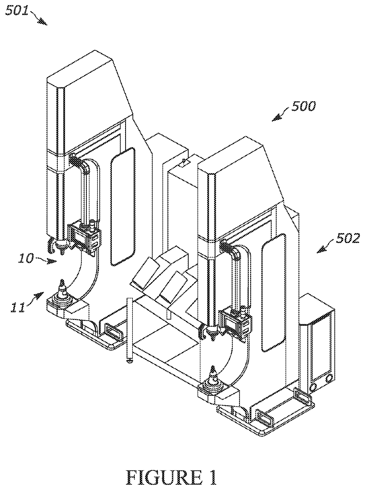
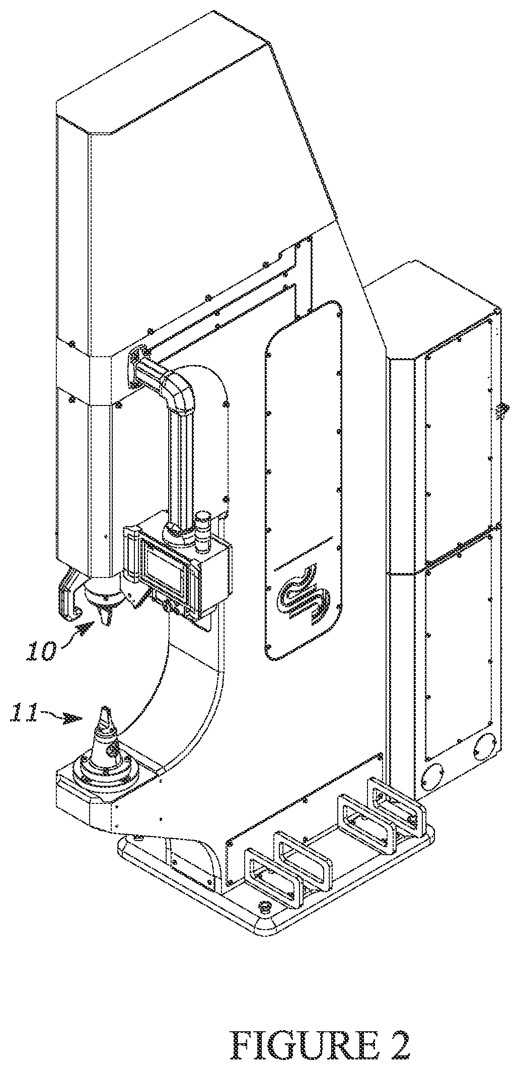
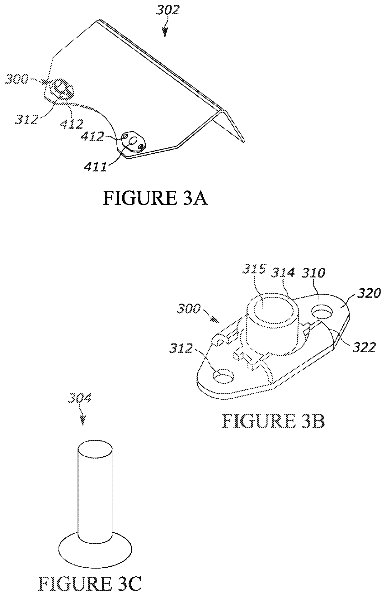
[0047]Referring now to the drawings and in particular to FIGS. 1 and 2, the upper drill tool is shown generally at 10. In one application, the drill tool is configured to drill openings through a bracket, such as bracket 302 (FIG. 3A), while other uses are contemplated. In such a use, ...


PUM

PropertyMeasurementUnit
Areaaaaaaaaaaa

Abstract

A lower drill tool that is structurally configured to receive a bracket, and, to cooperate with an upper drill tool having a pair of spaced apart drill bits. The lower drill tool has part receiving surface, a pair of spaced apart drill bores, a central bore, a centering nub and a biasing member. The drill bores extend downwardly away from the part receiving surface. The central bore is between the drill bores and extends downwardly away from the part receiving surface. The centering nub is slidable within the central bore, and has an upper tip extendable beyond the part receiving surface, positionable between an extended position and a partially retracted position. The upper tip has a conical configuration. The biasing member is positioned within the central bore and biases the centering nub toward the extended position. A drill system and a method are also disclosed.

Description

CROSS-REFERENCE TO RELATED APPLICATION[0001]This application claims priority from U.S. Provisional Patent Application Ser. No. 62 / 971,929 filed on Feb. 8, 2020, entitled “SYSTEM AND METHOD FOR COUPLING FASTENER HARDWARE TO A BRACKET”, and claims priority from U.S. Provisional Patent Application Ser. No. 63 / 031,882 filed on May 29, 2020, entitled “SYSTEM AND METHOD FOR COUPLING FASTENER HARDWARE TO A BRACKET”, the entire disclosure of which is hereby incorporated by reference in its entirety.BACKGROUND OF THE DISCLOSURE1. Field of the Disclosure[0002]The disclosure relates in general to a drill assembly, and more particularly, to a lower drill tool that is utilized to dimensionally position brackets so as to make highly dimensionally precise openings therethrough, including an upper drill tool, a lower drill tool and a method use of the lower drill tool. An overall drill system is likewise disclosed.2. Background Art[0003]In many applications it may be necessary to join components to...

Claims


Application Information

Patent Timeline
IPC IPC(8): B23B51/00B23B51/02
CPCB23B51/0054B23B2251/24B23B51/02B24B3/26B21J15/02B21J15/32B21J15/36B21J15/30B23Q5/54B23P23/04B23B39/161B23B35/00B23Q15/0075B23Q16/00B23B31/028B23Q17/006B23Q17/2216B23B31/1075B23B51/107B23Q3/18B23Q3/183B21J15/14
Inventor RUSSELL, JOSEPH ROBERTTURMAN, JASON R.ANDERSON, RYAN NATHANMERINO, MARCOSVAN'T LAND, GABRIEL C.
Owner J R AUTOMATION TECH
Learn More