Air suspension pressure display

a pressure display and air suspension technology, applied in suspensions, optical signalling, signalling/lighting devices, etc., can solve the problems of difficult reading of gauges, time-consuming and laborious, and the inability of people loading trailers to monitor air pressure, etc., to achieve simple and easy-to-read

Active Publication Date: 2015-02-05
QUESTAR VENTURES
View PDF4 Cites 2 Cited by
  • Summary
  • Abstract
  • Description
  • Claims
  • Application Information

AI Technical Summary

Benefits of technology

[0006]According to the invention, a series of lights provides a simple and easy-to-read display of the relative air pressure within the air springs. In one embodiment, various lights will light up when the air pressure is below, at, or above the appropriate air pressure. The color and number of lights can be varied. The lights may be located conveniently at the side of the trailer so that the load operator can easily see them.

Problems solved by technology

Therefore, a person loading a trailer would not be able to monitor the air pressure without either periodically going inside the cab or to the side of the trailer or communicating in some manner with a person reading the gauges.
This is both time-consuming and prone to error (e.g. if there is an error in communications between the load operator and the person within the cab).
In addition, the gauges may be difficult to read, especially at night.
All of the above create a safety issue.

Method used


Image

  • Air suspension pressure display
  • Air suspension pressure display
  • Air suspension pressure display

Examples


Embodiment Construction

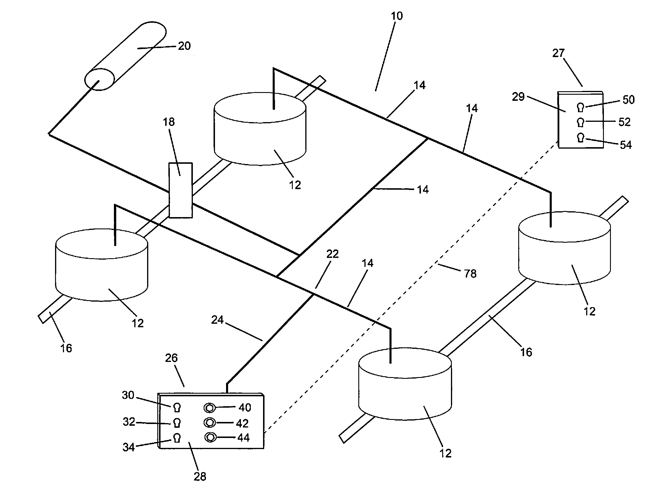
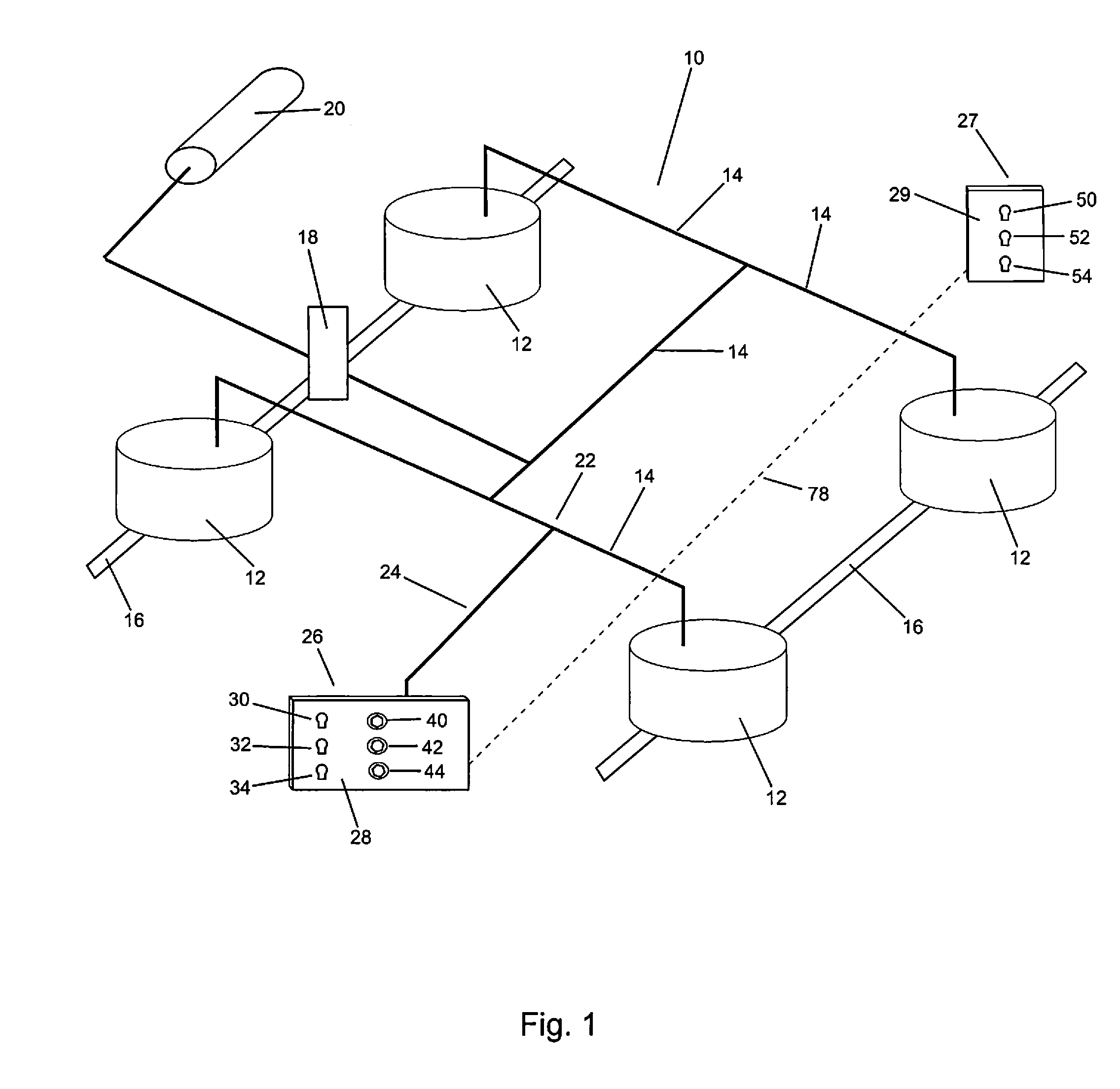
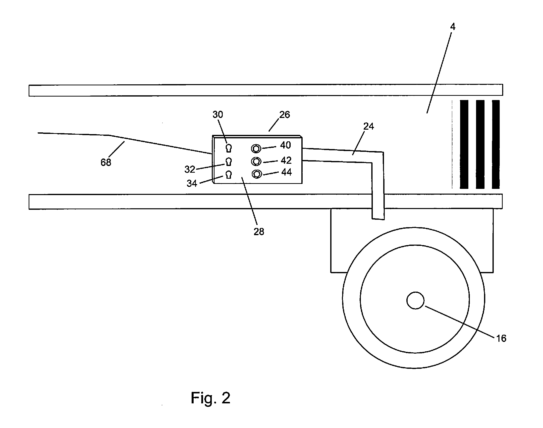
[0030]Referring to FIGS. 1 and 2, an air suspension system 10 for a vehicle comprises a plurality of air springs 12. The vehicle may be a trailer, a truck, or another similar device. The air springs 12 support the chassis 4 of the vehicle on the axles 16 and are connected together through air intake lines 14 that feed air into the air springs 12. As air is fed into the air springs 12, the air springs 12 inflate, raising the chassis 4 from the axles 16 (and thereby increasing the ride height). A levelling valve 18 controls the flow of air into the air intake lines 14 from an air compressor 20. For example, the levelling valve 18 allows for air to be fed into the air intake lines 14 until a certain ride height is reached, at which time, the levelling valve 18 prevents further air from being fed into the air intake lines 14. Along one of the air intake lines 14, a T-joint 22 is provided. A secondary air line 24 extends from one arm of the T-joint 22 to a detection unit 26.

[0031]As show...


PUM


Abstract

A system for displaying the relative air pressure in an air suspension system for a vehicle comprises an intake line connecting from the air suspension system to a manifold. One or more pressure switches are connected to the manifold. A corresponding light is attached to each of the pressure switches. When the pressure within the manifold reaches preconfigured levels, one of the pressure switches is closed, and a corresponding light is illuminated. The lights are located on the side of the vehicle such that they can be easily seen.

Description

REFERENCES TO RELATED APPLICATIONS[0001]This application claims the benefit of U.S. Provisional Application No. 61 / 859,863 filed Jul. 30, 2013 and U.S. Provisional Application No. 61 / 945,728 filed Feb. 27, 2014, the contents of all of which are hereby incorporated by reference.FIELD OF THE INVENTION[0002]The invention relates to the field of air suspension systems for trucks and trailers, and in particular, to displays for informing operators about the pressure level in air suspension systems.BACKGROUND OF THE INVENTION[0003]Air suspension systems are used in vehicles to provide a smooth and constant ride. They may be found in all types of vehicles, including in particular, trucks and trailers. An air pump or air compressor pressurizes the air within one or more air bags (or air springs), raising the chassis of the vehicle from the axles. Typically, the air springs are inflated with pressurized air until a certain ride height is reached (the ride height being the distance between th...

Claims


Application Information

Patent Timeline
Patent Type & Authority Applications(United States)
IPC IPC(8): B60K35/00
CPCB60K35/00B60G2202/152B60G2400/51222B60G2600/042
Inventor ROBERTS, BYRON
Owner QUESTAR VENTURES
Why Eureka
Try Eureka