
Head-mount eye tracking system

a tracking system and head mount technology, applied in the field of eye tracking systems, can solve the problems of high cost, complex operation, and strong eye discomfort, and achieve the effect of reducing the problem of wrong determination and shielding of the sight lin

Active Publication Date: 2015-02-05
NAT CHIAO TUNG UNIV
View PDF2 Cites 22 Cited by
  • Summary
  • Abstract
  • Description
  • Claims
  • Application Information

AI Technical Summary

Benefits of technology

The invention is a head-mount eye tracking system that solves problems of incorrect vision and blocking the sight line. It captures environmental and pupil images and maps them together to improve accuracy. The system also fixes the light source and capturing device around the user's eye to avoid shielding the sight line.

Problems solved by technology

A disadvantage of the contact eye tracking technique is that contact of a foreign matter may cause strong eye discomfort, and eye and / or skin secretions may cause signal interference.
However, the existing free-head eye tracking technique is still required to resolve a problem of errors caused by movement of user's head.
Moreover, the free-head eye tracking technique also has disadvantages of complex in operation and high cost, etc.
However, since the existing head-mount eye tracking technique determines the gazing position of the user only according to the eye information (the pupil image), it is easy to make a wrong determination.
Moreover, the existing head-mount eye tracking technique generally has a problem that a sight line is shielded by the head-mount eye tracking system, which causes inconvenience in utilization.

Method used


Image

  • Head-mount eye tracking system
  • Head-mount eye tracking system
  • Head-mount eye tracking system

Examples


first embodiment

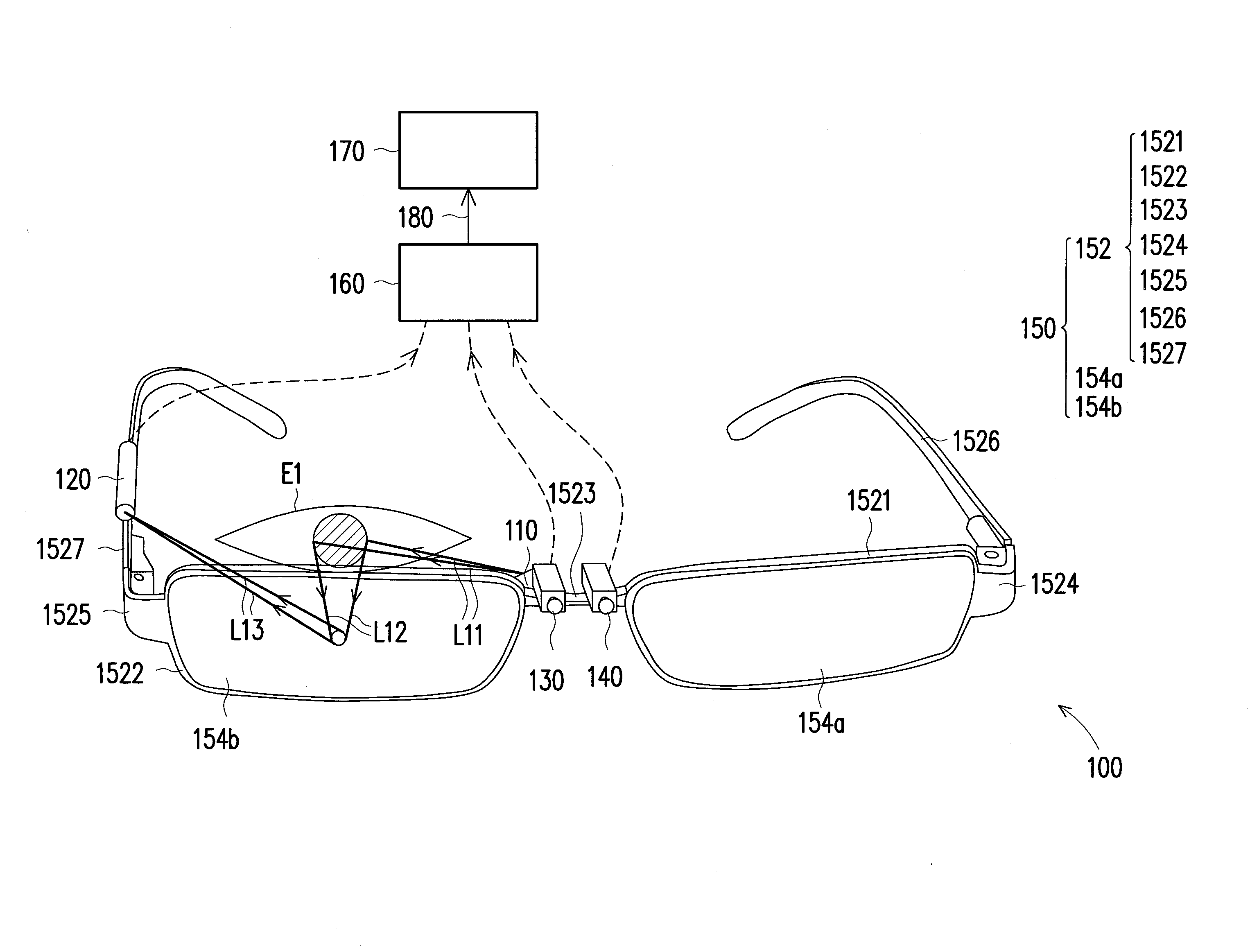
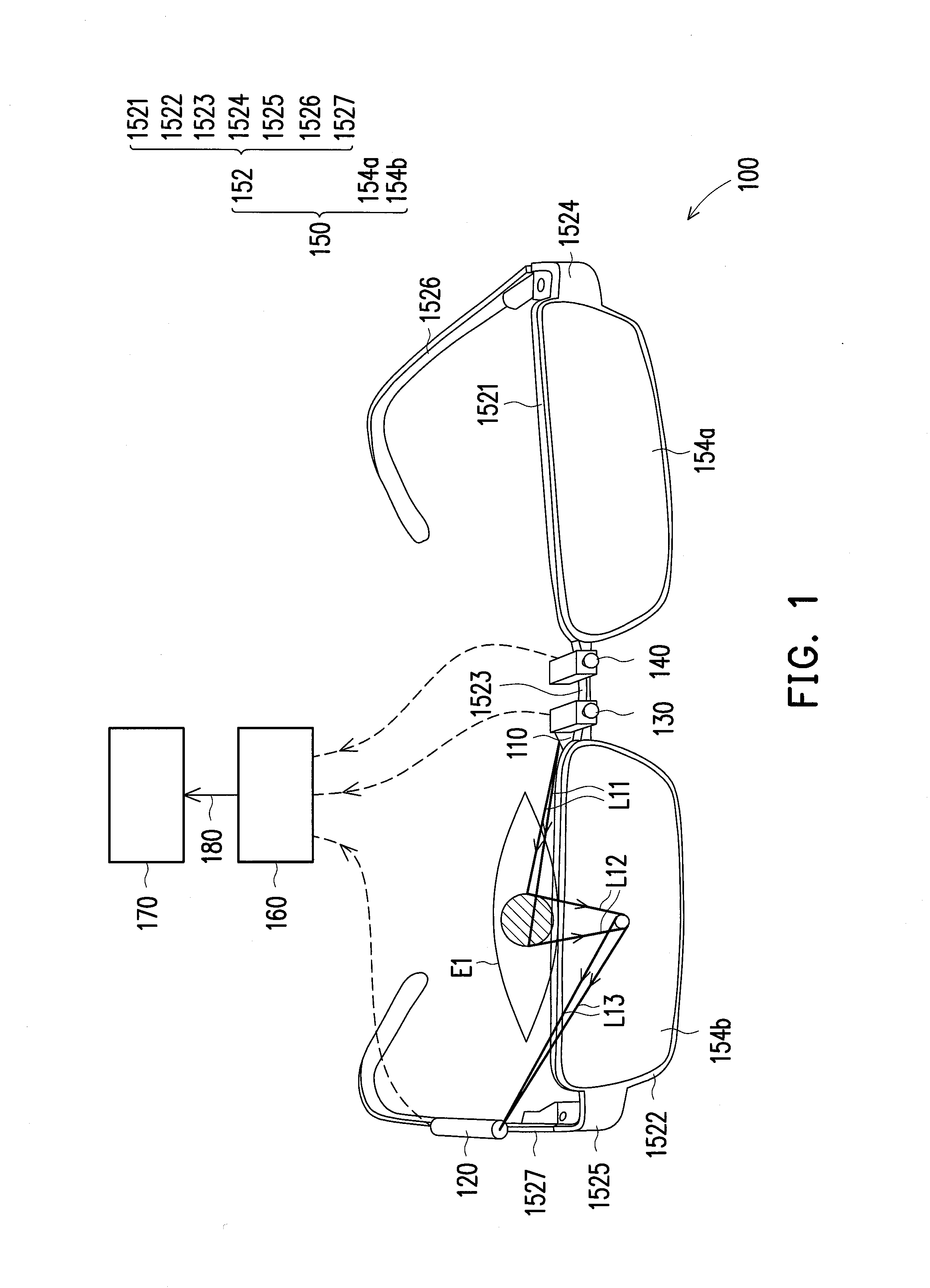
[0024]FIG. 1 is a side view of a head-mount eye tracking system according to the invention. Referring to FIG. 1, the head-mount eye tracking system 100 includes a first light source 110, a first pupil image capturing device 120, a first environmental image capturing device 130, a second environmental image capturing device 140, a fixing device 150 and an image identification system 160, wherein the fixing device 150 is suitable to be mounted on the head of a user (not shown), so as to fix the first light source 110, the first pupil image capturing device 120, the first environmental image capturing device 130 and the second environmental image capturing device 140 around a first eye El of the user.

[0025]The fixing device 150 can be a pair of glasses, a headcloth, a hat or a cap, etc. that is suitable for fixing the above elements on the head and is suitable for being removed from the head, so as to achieve better flexibility and convenience. In the present embodiment, the fixing dev...

second embodiment

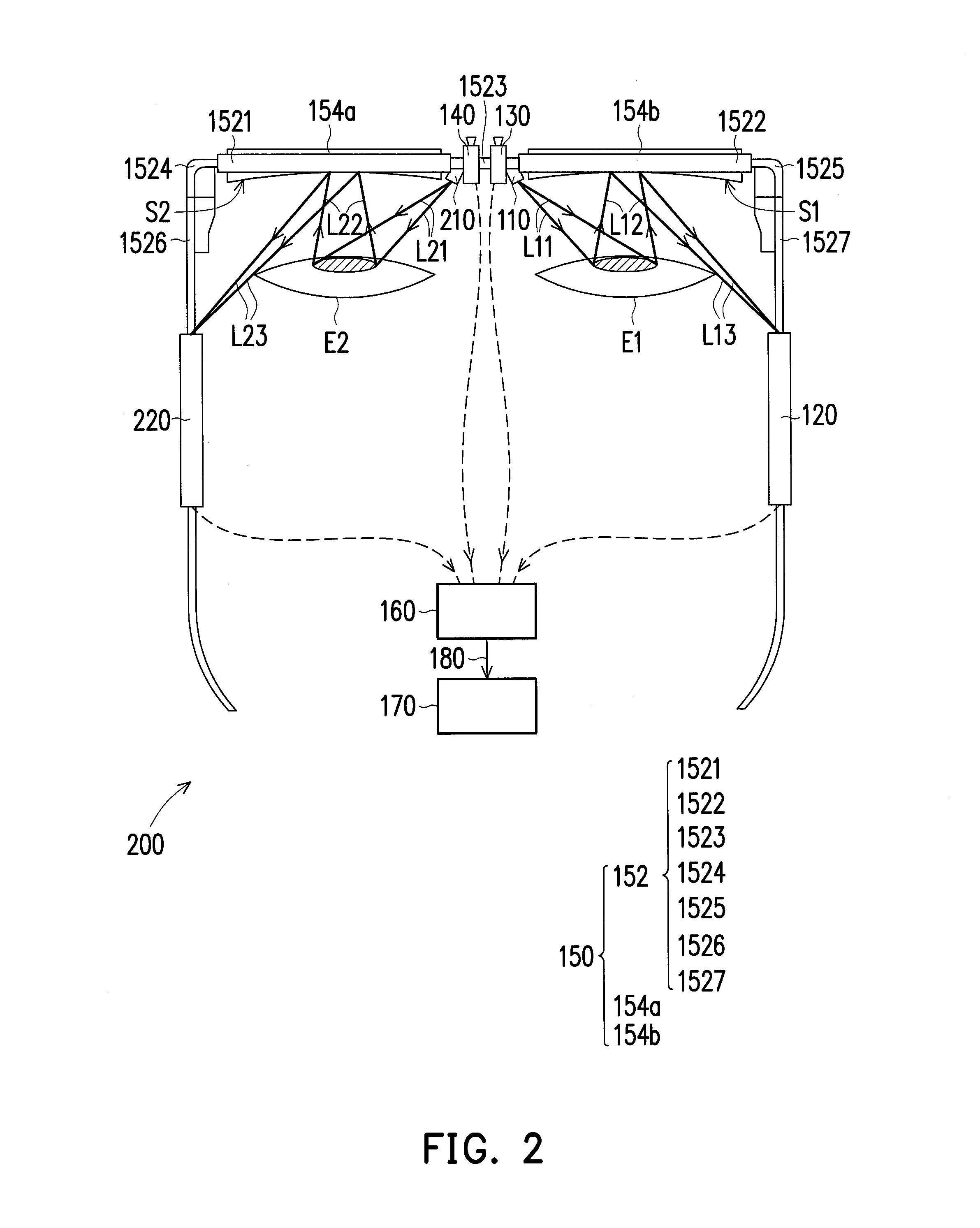
[0038]FIG. 2 is a top view of a head-mount eye tracking system according to the invention. Referring to FIG. 2, the head-mount eye tracking system 200 of the present embodiment has similar elements, effects and application range with that of the head-mount eye tracking system 100 of FIG. 1. A main difference therebetween is that the head-mount eye tracking system 200 of the present embodiment further includes a second light source 210 and a second pupil image capturing device 220. Moreover, the second light source 210 and the second pupil image capturing device 220 are fixed on the fixing device 150. In the present embodiment, the fixing device 150 fixes the second light source 210 and the second pupil image capturing device 220 around the second eye E2, but the invention is not limited thereto.

[0039]In the present embodiment, the second light source 210 is, for example, disposed on the first connection portion 1523, and the second pupil image capturing device 220 is, for example, d...


PUM


Abstract

A head-mount eye tracking system including a first light source, a first pupil image capturing device, a first and a second environmental image capturing devices, a fixing device and an image identification system. The first light source is applied to illuminate a first eye of a user. The first pupil image capturing device is applied to capture a first pupil image of the first eye. The first and the second environmental image capturing devices are respectively applied to capture a first and a second environmental images in front of the user. The fixing device is mounted to the head of the user to fix the first light source, the first pupil image capturing device, the first and the second environmental image capturing devices on the head of the user. The image identification system is applied to map the first or the second environmental images to the first pupil image.

Description

CROSS-REFERENCE TO RELATED APPLICATION[0001]This application claims the priority benefit of Taiwan application serial no. 102127317, filed on Jul. 30, 2013. The entirety of the above-mentioned patent application is hereby incorporated by reference herein and made a part of this specification.BACKGROUND[0002]1. Technical Field[0003]The invention relates to an eye tracking system. Particularly, the invention relates to a head-mount eye tracking system.[0004]2. Related Art[0005]Presently, an eye tracking technique is mainly divided into a contact eye tracking technique that requires contacting the eye and a non-contact eye tracking technique without contacting the eye. The contact eye tracking technique mainly includes a search-coil (SC) method and an electro-oculography (EOG) method, and the non-contact eye tracking technique mainly includes a free-head eye tracking technique and a head-mount eye tracking technique.[0006]Regarding the contact eye tracking technique, taking the SC meth...

Claims


Application Information

Patent Timeline
IPC IPC(8): G06F3/01G02B27/01
CPCG02B27/017G06F3/013A61B3/113G02B2027/0138G02B2027/0178G02B2027/0187G06F3/015
Inventor OU-YANG, MANGCHIOU, JIN-CHERNHUANG, TING-WEIHU, CHUN-CHENGJHUANG, JYUN-WEI
Owner NAT CHIAO TUNG UNIV
Learn More